Offset suppression in micromachined lorentz force magnetic sensor by current chopping

a technology of offset suppression and micro-machined lorentz force magnetic sensors, applied in the direction of magnetic measurement, magnetic field offset compensation, magnetic field measurement using permanent magnets, etc., can solve the problem of more than 1° azimuth determination error, drift error, and reducing the dynamic range of the system

Active Publication Date: 2017-03-02
RGT UNIV OF CALIFORNIA
View PDF3 Cites 7 Cited by
  • Summary
  • Abstract
  • Description
  • Claims
  • Application Information

AI Technical Summary

Problems solved by technology

Offset reduces the dynamic range of the system and also results in drift error, which directly transfers to heading error when the sensor is used as a compass.
A 1 μT drift error in the sensor output may result in more than 1° error in azimuth determination.
However, offset and offset instability in the Lorentz force sensor has not been well-studied as yet.
Both of the above works indicated that despite the low short-term noise of the Lorentz force sensor, long-term drift is a problem when using this sensor as an electronic compass.

Method used


Image

  • Offset suppression in micromachined lorentz force magnetic sensor by current chopping
  • Offset suppression in micromachined lorentz force magnetic sensor by current chopping
  • Offset suppression in micromachined lorentz force magnetic sensor by current chopping

Examples


Embodiment Construction

[0031]A method and apparatus is disclosed for suppressing the offset and reducing the offset instability in micromachined Lorentz force magnetic sensors. The disclosed mechanism is suitable for use in all Lorentz force magnetic sensors operating under the same principle.

I. THE CURRENT CHOPPING METHOD

[0032]A. Basic Principle of a Lorentz Force Magnetometer

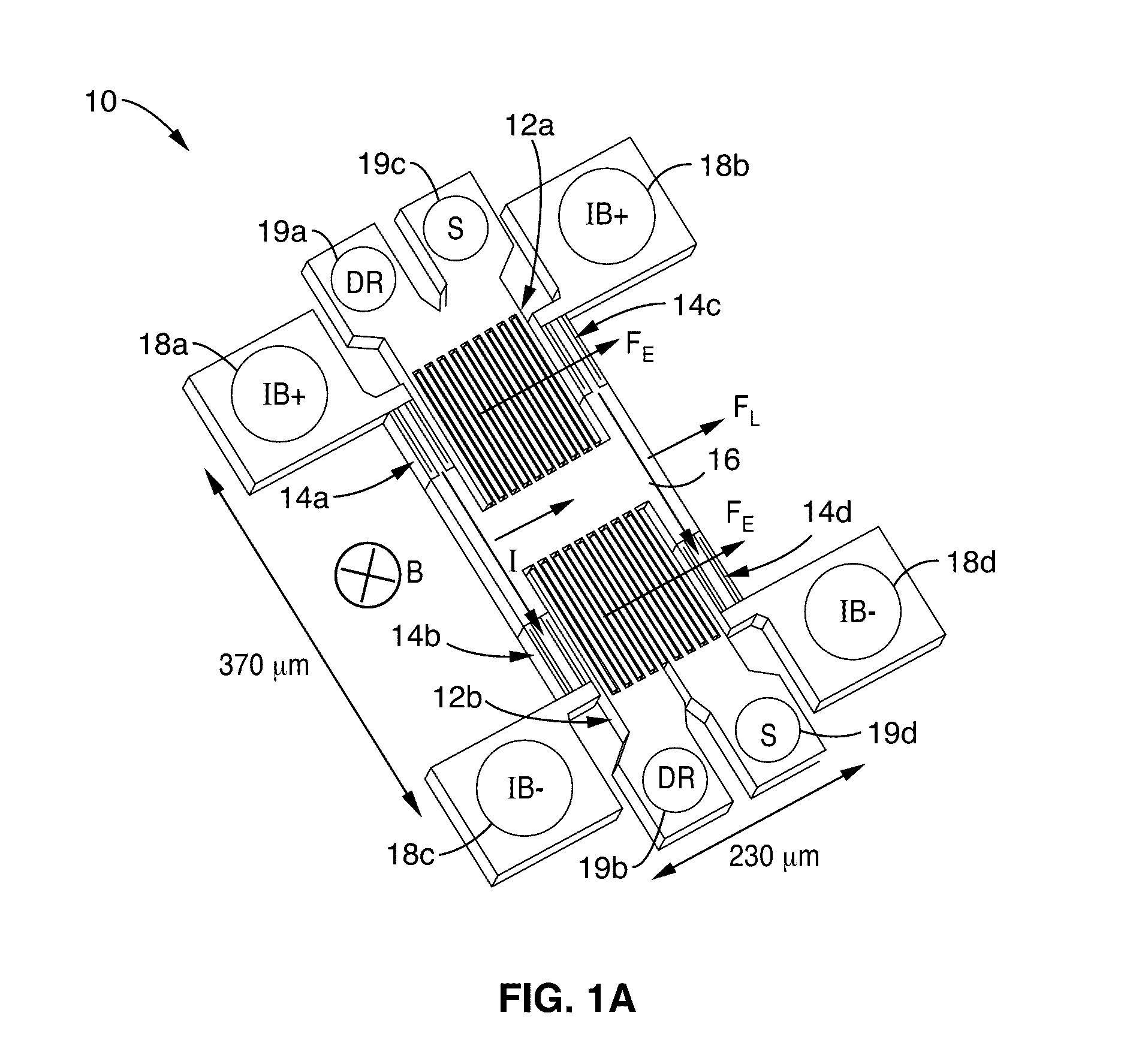
[0033]FIG. 1A illustrates an example embodiment 10 of a Lorentz force magnetometer, in which the Lorentz force is modulated at the mechanical resonance frequency fn of the proof-mass. The example magnetometer shown has an fn of 105.51 kHz, a Q of 13,000, RIB of 155 ohms (Ω), a device thickness of 40 μm, a width of 230 μm, and a length of 370 μm. It will be recognized that the present disclosure is not limited to devices having these specific characteristics, or dimensions.

[0034]Parallel plates 12a and 12b are used for electrostatic sensing and electrostatic driving, respectively, of a proof mass 16 suspended by a plurality of folded...


PUM


Abstract

Offsets (short and long term) are significantly reduced in a Lorentz force magnetometer circuit. A modulated bias current supplied to the magnetometer is chopped by periodically switching its polarity. Magnetometer output is demodulated, then de-chopping performed to restore signal polarity output. Chopping of the bias current signal polarity modulates magnetic field signal to a frequency in which electrostatic force remains constant toward eliminating offset and long-term drift from said micromechanical resonator.

Description

CROSS-REFERENCE TO RELATED APPLICATIONS[0001]This application is a 35 U.S.C. §111(a) continuation of PCT international application number PCT / US2014 / 068404 filed on Dec. 3, 2014, incorporated herein by reference in its entirety, which claims priority to, and the benefit of, U.S. provisional patent application Ser. No. 61 / 911,087 filed on Dec. 3, 2013, incorporated herein by reference in its entirety. Priority is claimed to each of the foregoing applications.[0002]The above-referenced PCT international application was published as PCT International Publication No. WO 2015 / 084980 on Jun. 11, 2015, and republished on Sep. 17, 2015, which publications are incorporated herein by reference in their entireties.STATEMENT REGARDING FEDERALLY SPONSORED RESEARCH OR DEVELOPMENT[0003]This disclosed material was made with Government support under Grant No. 0846379, awarded by the National Science Foundation. The Government has certain rights in this invention.INCORPORATION-BY-REFERENCE OF COMPUTE...

Claims


Application Information

Patent Timeline
Patent Type & Authority Applications(United States)
IPC IPC(8): G01R33/00G01R33/038
CPCG01R33/0017G01R33/0041G01R33/0385
Inventor HORSLEY, DAVIDLI, MO
Owner RGT UNIV OF CALIFORNIA
Why Eureka
Try Eureka