
Keyboard switch

a keyboard switch and switch body technology, applied in the direction of switch side location, emergency actuator, contact mechanism, etc., can solve the problems of increasing the thickness of the keyboard switch, inconvenient use, button slanting or getting stuck, etc., to prevent the slant of the button, convenient operation and use, and good touch sens

Active Publication Date: 2017-03-02
WU FUXI
View PDF3 Cites 4 Cited by
  • Summary
  • Abstract
  • Description
  • Claims
  • Application Information

AI Technical Summary

Benefits of technology

The invention is a keyboard switch with an X-shaped rack structure that prevents the button from slanting or getting stuck when pressed. The rack structure is made up of two connecting racks with X-shaped structures at the ends. The racks are symmetrically placed on either side of the button, and when the user presses the button from a tilt angle, the rotation of balancing levers in the racks can offset pressing force distribution in the slanting direction to ensure that the button remains upright and prevents jamming. The balancing levers can be rotated and installed on the button and base through lever bodies, reducing friction between the button and the base and avoiding slanting of the button. Overall, this design provides better sensory feedback, makes the switch more convenient, and prevents slanting and jamming of the button.

Problems solved by technology

However, the contact area of the positioning column and the base is usually small, and the button tends to tilt or get stuck when being pressed.
The pressing part of the button is a guide pillar, which increases the thickness of the keyboard switch, and the use thereof is inconvenient.
In addition, the buttons are not easy to distinguish by touch, leading to unsatisfactory user experience.

Method used


Image

  • Keyboard switch
  • Keyboard switch
  • Keyboard switch

Examples


Embodiment Construction

[0024]The invention is described hereinbelow with reference to the accompanying drawings.

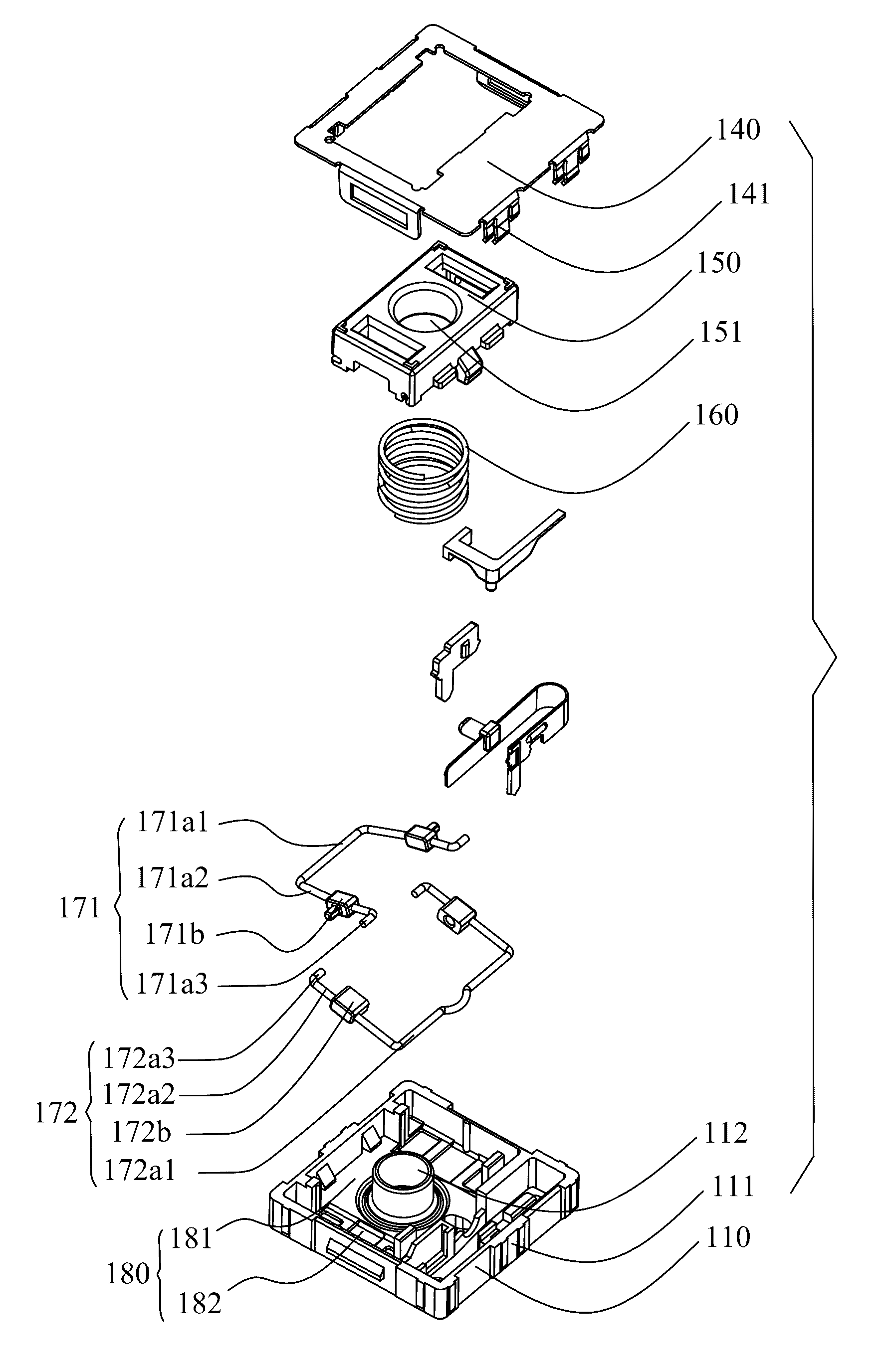
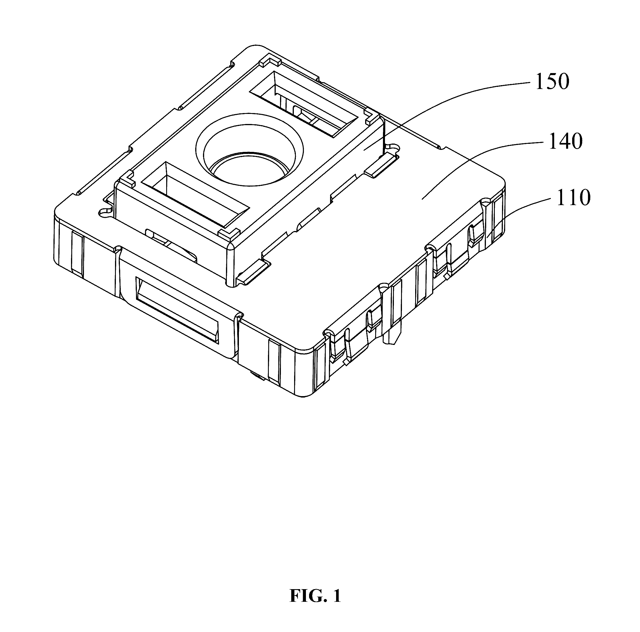
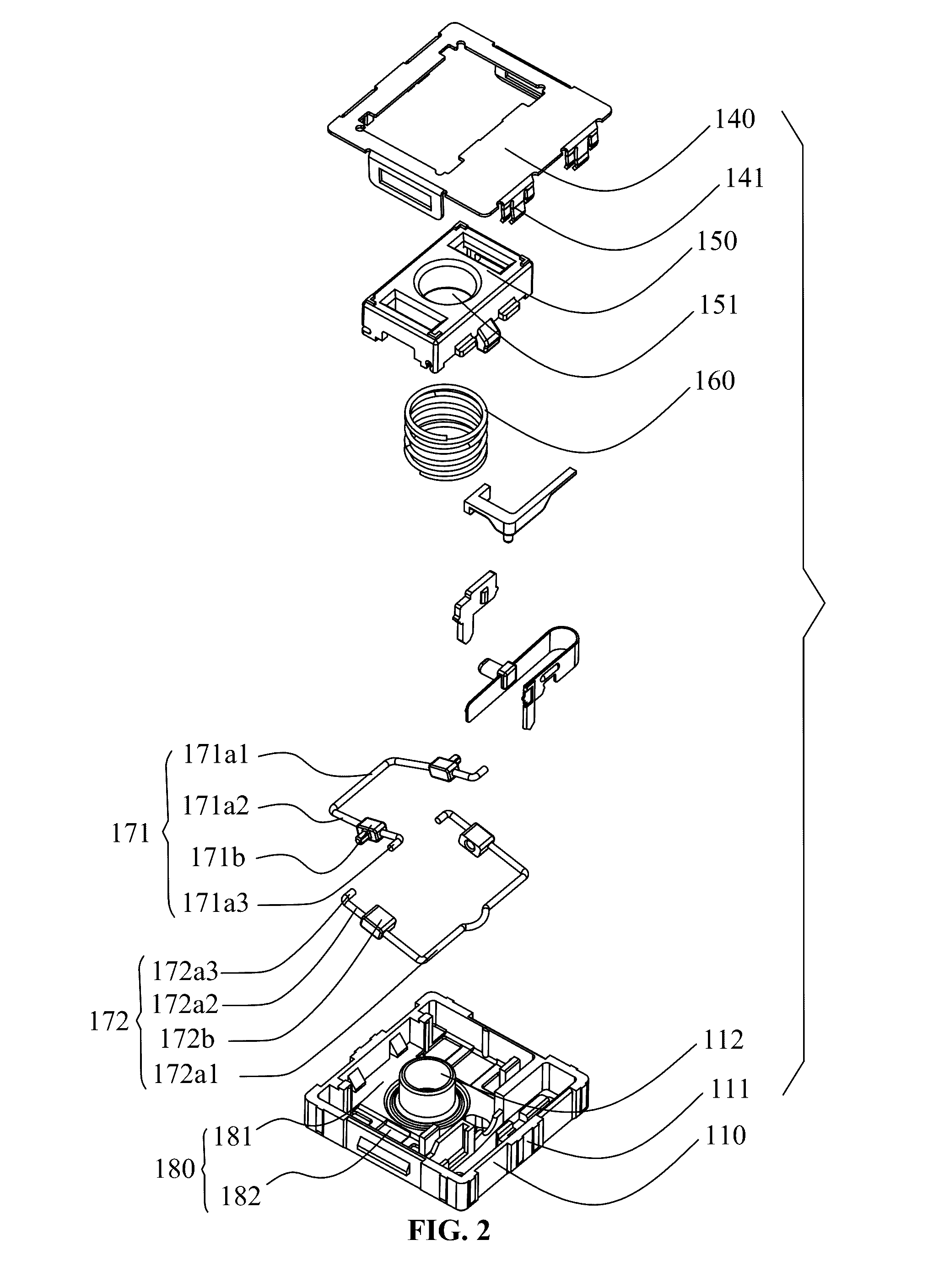
[0025]FIGS. 1-5 respectively show a stereogram, explosive view, sectional view, bottom view and exploded view of a keyboard switch of the invention. The keyboard switch 100 has X-shaped rack structure 170, and comprises a base 110, a static contact, a moving contact, an upper cover 140, a button 150, and a reset spring 160. The button 150 operates to control the contact of the static contact and the moving contact, and the reset spring 160 operates to control the reset of the button 150.

[0026]The upper cover 140 is buckled on the base 110, and both the static contact and the moving contact are disposed on the base 110. One end of the button 150 is installed on the base 110 and is capable of moving upwards and downwards, another end thereof passes through the upper cover 140, and both ends of the reset spring 160 abut against the button 150 and the base 110, respectively. The keyboard switch furt...


PUM


Abstract

A keyboard switch, including a base; a static contact; a moving contact; an upper cover; a button; a reset spring; an X-shaped rack structure; and a holding part. The X-shaped rack structure includes a first connecting rack and a second connecting rack. The first connecting rack includes a first balancing lever and two first connecting parts sleeving on the first balancing lever, the second connecting rack includes a second balancing lever and two second connecting parts sleeving on the second balancing lever; opposite surfaces of the two first connecting parts each are provided with one boss, facing surfaces of the two second connecting parts each are provided with one round hole, and the boss is inserted in the round hole so that two ends of the two first connecting racks and two ends of the two second connecting racks are connected to form two X-shaped structures.

Description

CROSS-REFERENCE TO RELATED APPLICATIONS[0001]Pursuant to 35 U.S.C. §119 and the Paris Convention Treaty, this application claims the benefit of Chinese Patent Application No. 201520652289.5 filed Aug. 27, 2015, the contents of which are incorporated herein by reference. Inquiries from the public to applicants or assignees concerning this document or the related applications should be directed to: Matthias Scholl P. C., Attn.: Dr. Matthias Scholl Esq., 245 First Street, 18th Floor, Cambridge, Mass. 02142.BACKGROUND OF THE INVENTION[0002]Field of the Invention[0003]The invention is related to a keyboard switch, and more particularly to a keyboard switch.[0004]Description of the Related Art[0005]Conventionally, an individual keyboard switch includes a base and a button including a positioning column. The positioning column is capable of moving upward and downward in the opening of the base to activate the circuit. However, the contact area of the positioning column and the base is usua...

Claims


Application Information

Patent Timeline
Patent Type & Authority Applications(United States)
IPC IPC(8): H01H13/14H01H13/28H01H13/85H01H13/52
CPCH01H13/14H01H13/52H01H2013/525H01H13/85H01H13/285H01H3/125H01H2221/058H01H2225/028H01H3/42H01H15/102
Inventor WU, FUXI
Owner WU FUXI
Learn More