LED illumination device

a technology of illumination device and led light, which is applied in the direction of lighting apparatus, electrical equipment, light sources, etc., can solve the problems of insufficient reduction of total harmonic distortion (thd) and noise of harmonics

Active Publication Date: 2017-03-23
CITIZEN WATCH CO LTD +1
View PDF0 Cites 51 Cited by
  • Summary
  • Abstract
  • Description
  • Claims
  • Application Information

AI Technical Summary

Benefits of technology

[0027]The purpose and the effect of the present invention will be recognized and obtained by using components that are pointed out particularly in the claims and combinations thereof. Both the foregoing general explanation and the following detailed explanation are merely illustrative and explanatory and do not limit the present invention described particularly in the claims.

Problems solved by technology

Consequently, in the light source circuit 2600, harmonic noise occurs and the total harmonic distortion (THD) is not reduced sufficiently.

Method used


Image

  • LED illumination device
  • LED illumination device
  • LED illumination device

Examples


Embodiment Construction

[0051]Hereinafter, with reference to the drawings, embodiments of an LED illuminator according to the present invention are described in detail. However, it should be noted that the technical scope of the present invention is not limited to those embodiments but encompasses the inventions described in the claims and the equivalents thereof. The dimension in each drawing does not reflect the exact dimension and sometimes the size of parts is drawn in an exaggerated manner or some parts are omitted for explanation. The same numerals are attached to the same elements and duplicated explanation is omitted.

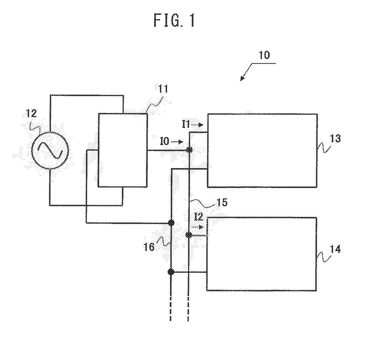
[0052]FIG. 1 is a block diagram of an LED illuminator 10.

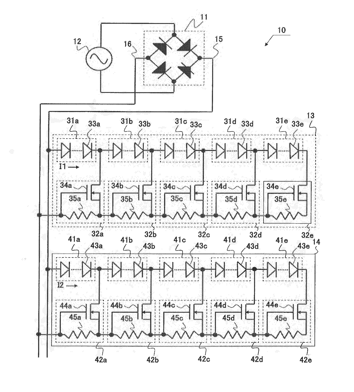
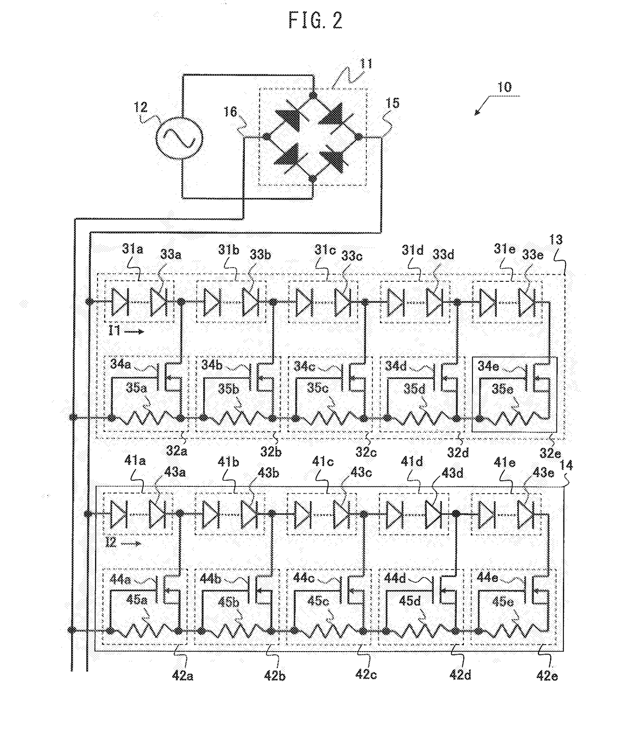
[0053]As illustrated in FIG. 1, the LED illuminator 10 includes a bridge rectifier circuit 11, a first LED drive circuit 13, and a second LED drive circuit 14. For convenience, in FIG. 1, a commercial AC power source 12 connected to the bridge rectifier circuit 11 is illustrated.

[0054]The commercial AC power source 12 connects to...


PUM


Abstract

An LED illuminator configured to further reduce total harmonic distortion is provided. The LED illuminator has: a first LED string including a first partial LED string and a second partial LED string; a second LED string including a third partial LED string and a fourth partial LED string; a first switching circuit configured to switch between a state where only the first partial LED string is connected to a rectifier and a state where the first partial LED string and the second partial LED string connected in series are connected to the rectifier as a full-wave rectified voltage waveform that is output from the rectifier increases/decreases; and a second switching circuit configured to switch between a state where only the third partial LED string is connected to the rectifier and a state where the third partial LED string and the fourth partial LED string connected in series are connected to the rectifier, and the switching timing by the first switching circuit and the switching timing by the second switching circuit are set so as to differ from each other.

Description

TECHNICAL FIELD[0001]The present invention relates to an LED illuminator including an LED drive circuit configured to drive an LED with a full-wave rectified waveform.BACKGROUND ART[0002]There is known an LED illuminator including an LED drive circuit having an LED string in which a plurality of LEDs is connected in series and configured to improve luminance and to prevent a flicker by increasing / decreasing the number of serial stages of the LED string in accordance with an increase / decrease in the voltage of the full-wave rectified waveform and by lengthening an on-state period. Among such LED drive circuits, there is an LED drive circuit configured to improve a power factor and a distortion factor by increasing / decreasing a current that flows through the LED string in accordance with an increase / decrease in the full-wave rectified waveform.[0003]FIG. 11 is a circuit diagram of a light source circuit 2600 described in Patent Document 1. The light source circuit 2600 includes a brid...

Claims


Application Information

Patent Timeline
Patent Type & Authority Applications(United States)
IPC IPC(8): H05B33/08H05B44/00
CPCH05B33/083H05B33/0827H05B33/0845H05B33/0815H05B45/48H05B45/46H05B45/10
Inventor AKIYAMA, TAKASHIOCHIAI, YUKI
Owner CITIZEN WATCH CO LTD
Why Eureka
Try Eureka