Light curtain installation method and interactive display apparatus

a technology of installation method and display apparatus, which is applied in the field of installation method of light curtain and interactive display apparatus, can solve the problems of difficult adjustment of the position or posture of the light curtain with respect to the image plan

Active Publication Date: 2017-03-30
SEIKO EPSON CORP
View PDF3 Cites 0 Cited by
  • Summary
  • Abstract
  • Description
  • Claims
  • Application Information

AI Technical Summary

Benefits of technology

[0013]In a case of employing this configuration, the user can easily recognize a position of the target region at which a check for whether or not it is possible to detect the contact of the object has to be performed and the user can check the installation state of the light curtain by checking for whether or not the operation with respect to the image plane causes the display of the marker to be stopped.
[0019]When the light curtain is not installed correctly, an error of a distance between light radiated from the light curtain and the image plane is great in a region apart from a light-emitting unit of the light curtain, that is, on a circumferential edge section of the image plane. In addition, ambient light travelling into the inner side of the image plane from the outside of the image plane has a great influence on the circumferential edge section of the image plane. Thus, when the target region is set to the circumferential edge section of the image plane, it is possible to efficiently check or adjust the installation state of the light curtain.
[0021]In a case of employing these configurations, it is possible to easily recognize whether or not it is possible to detect the contact of the object in the target region which extends in a line shape.

Problems solved by technology

Incidentally, since the light radiated from the light curtain expands in a plane shape, it is not easy to adjust the position or posture of the light curtain with respect to the image plane.

Method used


Image

  • Light curtain installation method and interactive display apparatus
  • Light curtain installation method and interactive display apparatus
  • Light curtain installation method and interactive display apparatus

Examples


Embodiment Construction

[0036]Hereinafter, embodiments of the invention will be described with reference to the accompanying drawings. The same reference signs are attached to corresponding components in each drawing and description thereof will not be repeated.

1. Outline

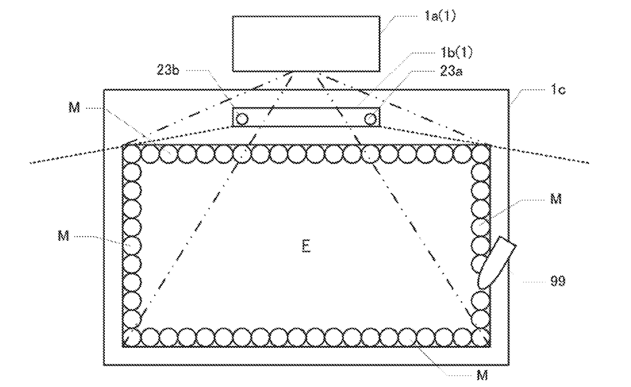
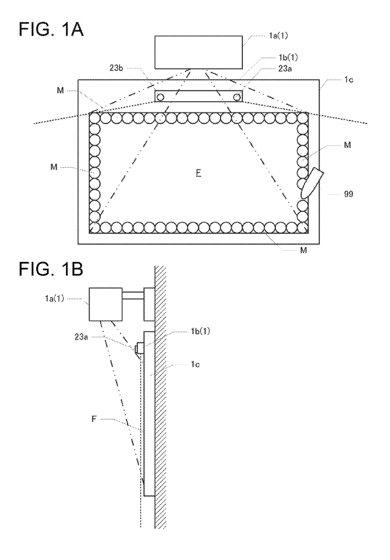
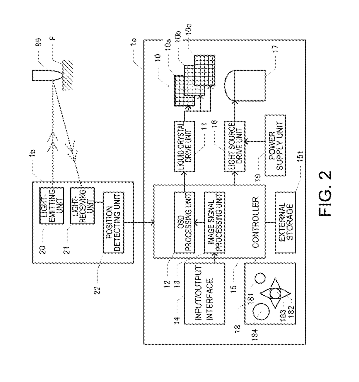
[0037]A projector 1 as an example of an interactive display apparatus according to the invention illustrated in FIGS. 1A and 1B is an apparatus that projects and displays an image to an image plane F. The projector 1 projects, to the image plane F, a synthesized image in which an external image formed based on an image signal input from an external device such as a PC or a smart phone and an image of an object corresponding to an operation with respect to a projected surface are synthesized. The projector 1 includes a first housing 1a in which a display unit is accommodated and a second housing 1b in which a light-emitting unit that radiates light with an infrared wavelength as illustrated in dotted lines in FIGS. 1A and 1B in a plane shap...


PUM


Abstract

A light curtain installation method, which is a method for adjusting or checking an installation state of a light curtain for detecting an operation with respect to an image plane of a display apparatus, includes: determining whether or not it is possible to detect an object that comes into contact with a target region on the image plane which corresponds to a reference pixel which is a pixel at a predetermined position; and setting a drive state of the reference pixel such that the drive state of the reference pixel is different depending on a result of the determining.

Description

BACKGROUND[0001]1. Technical Field[0002]The present invention relates to a light curtain installation method and an interactive display apparatus.[0003]2. Related Art[0004]Recently, an electronic blackboard or an interactive projector, which synthesizes and displays an image based on an image signal input from an external device and an image in which an object such as a character or a picture which corresponds to an operation with respect to an image plane, has been utilized in education and conferences. Such an interactive display apparatus is known, which detects an operation with respect to an image plane using a light curtain. The light curtain radiates light in a plane shape and receives direct or reflective light of the radiated light so as to detect a presence of an object such as a finger. When the light curtain for detecting the operation with respect to the image plane is installed, a position or posture of the light curtain with respect to the image plane needs to be adju...

Claims


Application Information

Patent Timeline
Patent Type & Authority Applications(United States)
IPC IPC(8): G06F3/042H04N9/31G06F3/041
CPCG06F3/0428H04N9/3194H04N9/3185G06F3/0418
Inventor IMAI, SHUNHONDA, YASUHIRO
Owner SEIKO EPSON CORP
Why Eureka
Try Eureka