Resting heart rate monitor system

a heart rate monitor and resting technology, applied in the field of resting heart rate monitor system, can solve the problems of cumbersome and obtrusive procedures

Active Publication Date: 2017-04-06
KONINKLIJKE PHILIPS ELECTRONICS NV
View PDF1 Cites 7 Cited by
  • Summary
  • Abstract
  • Description
  • Claims
  • Application Information

AI Technical Summary

Benefits of technology

[0007]It is an object of the present invention to provide a heart rate monitor system which i...

Problems solved by technology

This procedure is cumbersome and obtrusive as it requires refraining from eating and drinking for a s...

Method used


Image

  • Resting heart rate monitor system
  • Resting heart rate monitor system
  • Resting heart rate monitor system

Examples


Embodiment Construction

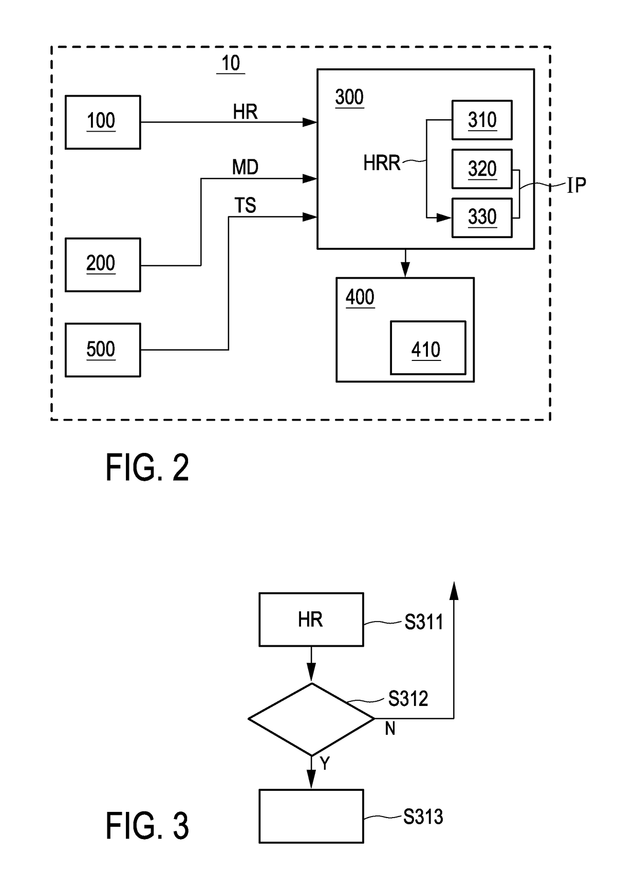
[0032]According to an aspect of the invention, a heart rate monitor system is provided which is used to measure a heart rate of a user. The heart rate monitor system can be implemented in a wrist device (like a smart watch) or other wearable devices, i.e. devices which can be attached or arranged on the skin of a user. The heart rate monitor system may comprise a heart rate sensor which can be optionally embodied as an optical sensor for determining the heart rate of a user.

[0033]The heart rate sensor according to the invention is a non-invasive heart rate sensor which is able to measure the electrical, acoustical or optical activity of the heart or the cardio-respiratory system.

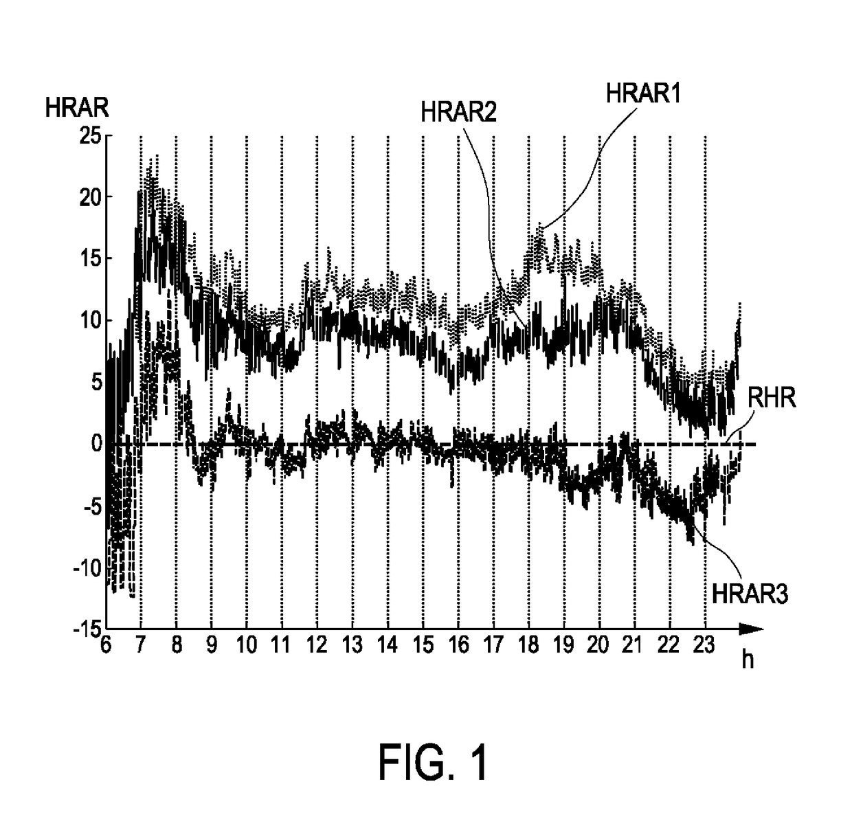
[0034]FIG. 1 shows a graph indicating a difference between a detected heart rate and a resting heart rate at different times of the day. FIG. 1 shows an example of a heart rate over time for mere illustrative purposes. On the x-axis, the hours of the day and on the y-axis, the heart rate above resting heart ...


PUM


Abstract

It is an object of the present invention to provide a heart rate monitor system (10) which is able to determine the resting heart rate in an effective and unobtrusive manner. In an aspect of the present invention, a heart rate monitor system (10) comprising an inactivity determining unit (320) for determining periods of inactivity (IP) of a user based on motion data (MD) detected by at least one motion sensor (200) attached to the user and a resting heart rate calculating unit (330) for calculating a resting heart rate (RHR) of the user based on heart rate data (HR) detected by at least one heart rate sensor (100) attached to the user during the periods of inactivity (IP) as determined by the inactivity determining unit (320) is provided.

Description

FIELD OF THE INVENTION[0001]The invention relates to a heart rate monitor system for measuring a heart rate of a user as well as a method of determining a resting heart rate of a user.BACKGROUND OF THE INVENTION[0002]The monitoring of a heart rate of a user for example by means of optical sensors is well known. Here, an optical sensor emits light into the skin of a user and the emitted light is scattered within the skin. Reflected light exits the skin and can be detected by an appropriate detector. Based on the received signals from the sensor, the heart rate of a user can be determined.[0003]Heart rate sensors are for example used for fitness applications. Here, the sensors can be worn as a wrist device or as forearm device, or as a device in contact to the skin in any other location of the body. Accordingly, the heart rate sensor will detect the heart rate of the user and can display the detected heart rate on the device or to a connected system such as a display on an electronic ...

Claims


Application Information

Patent Timeline
IPC IPC(8): A61B5/024A61B5/00A61B5/11
CPCA61B5/024A61B5/1118A61B2562/0219A61B5/6815A61B5/02416A61B5/681
Inventor BONOMI, ALBERTO GIOVANNIDE GROOT, KOEN THEO JOHAN
Owner KONINKLIJKE PHILIPS ELECTRONICS NV
Why Eureka
Try Eureka