
Chromatograph mass spectrometer and control method therefor

a mass spectrometer and chromatograph technology, applied in the field of chromatograph mass spectrometer, can solve the problems of not being able to automatically set an elution and taking time to determine sim measurement conditions, and achieve the effect of optimizing the measurement tim

Active Publication Date: 2017-04-06
HITACHI HIGH-TECH CORP
View PDF7 Cites 1 Cited by
  • Summary
  • Abstract
  • Description
  • Claims
  • Application Information

AI Technical Summary

Benefits of technology

The invention allows us to decide when we should measure peaks in waves without having to look at them on a computer screen first. This makes things easier because we don't have to spend extra time analyzing data that may or may not contain useful information.

Problems solved by technology

The technical problem addressed in this patent text relates to the lack of automation in selecting an optimal mass number for each peak during liquid chromatographic mass spectrometry measurements. Currently, a technician needs to manually decide which mass number should be measured for each targeted component, resulting in longer times for preparing and executing the measurement.

Method used


Image

  • Chromatograph mass spectrometer and control method therefor
  • Chromatograph mass spectrometer and control method therefor
  • Chromatograph mass spectrometer and control method therefor

Examples


Embodiment Construction

[0023]Hereinafter, description will be given of an embodiment of the invention with reference to drawings. Embodiments of the invention are not limited to the example described below, and various modifications can be made within a scope of the technical idea.

[Apparatus Configuration]

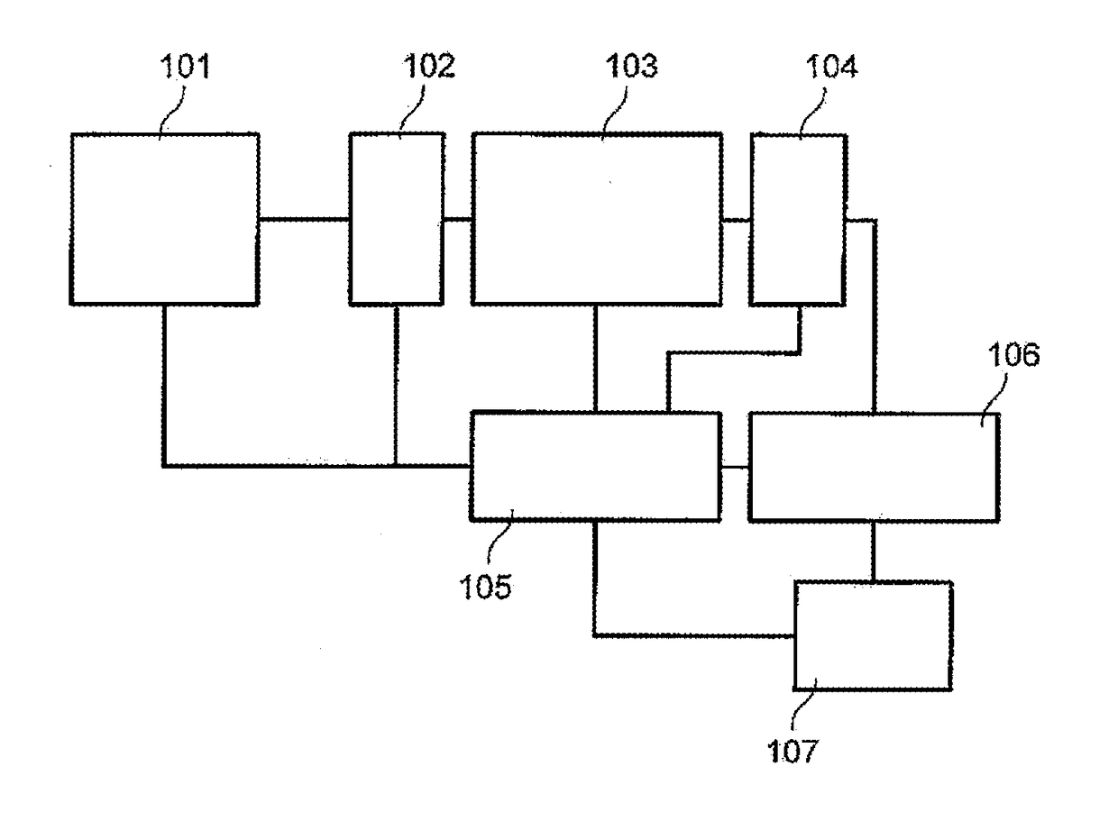
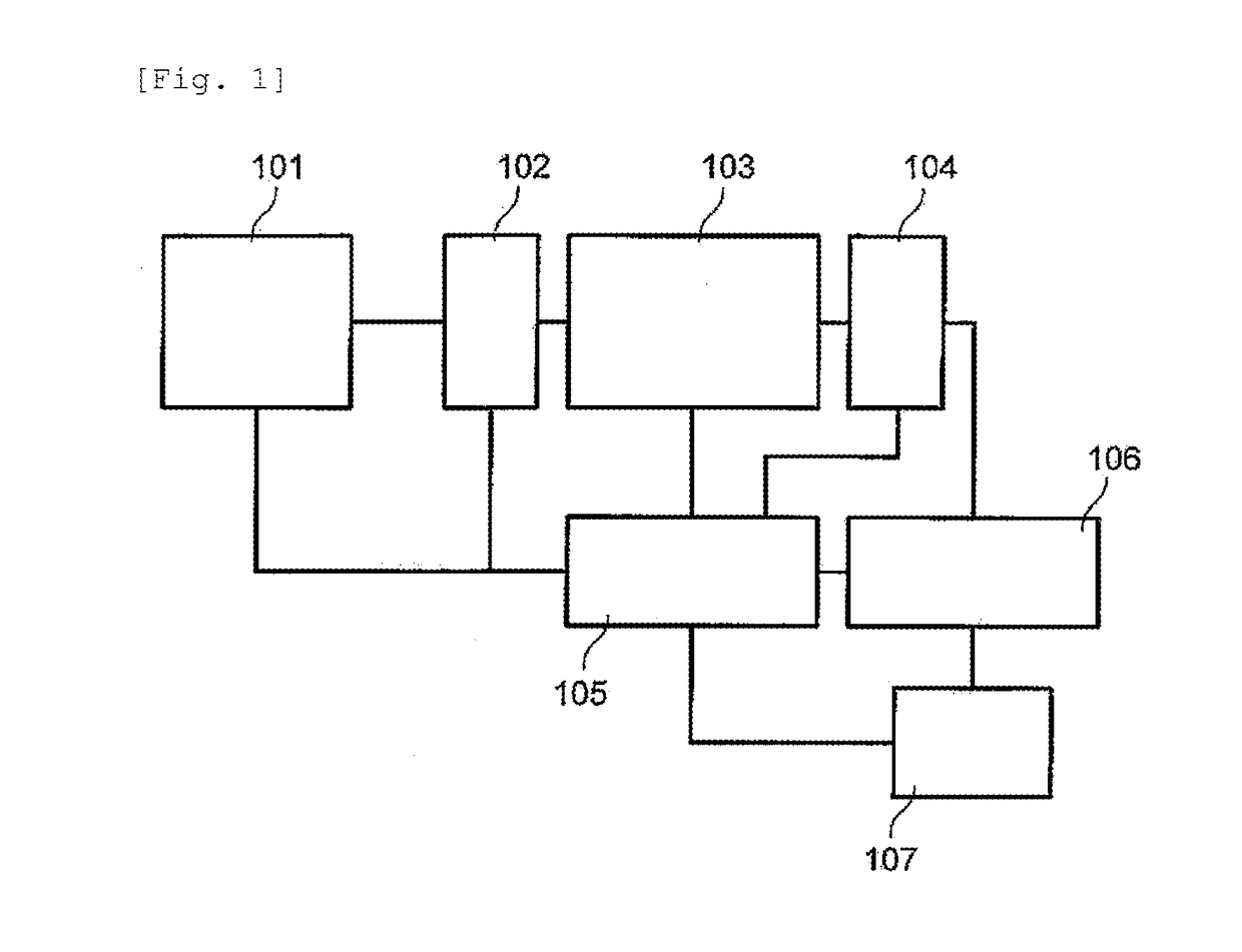
[0024]FIG. 1 illustrates an outline configuration of a liquid chromatography mass spectrometer. Many samples analyzed by the liquid chromatograph mass spectrometer are samples in which a plurality of components are present together. Thus, samples are purified by preprocessing or the like in accordance with the respective samples and are then separated by an LC (liquid chromatograph) unit 101. The samples after the separation are introduced into an ion source 102 of the mass spectrometer and is ionized. The ion source 102 as an ion generation unit uses an electrospray ionization method (ESI) or an atmospheric pressure chemical ionization method (APCI) that is typically used in a liquid chromatograph mass ...


PUM


Abstract

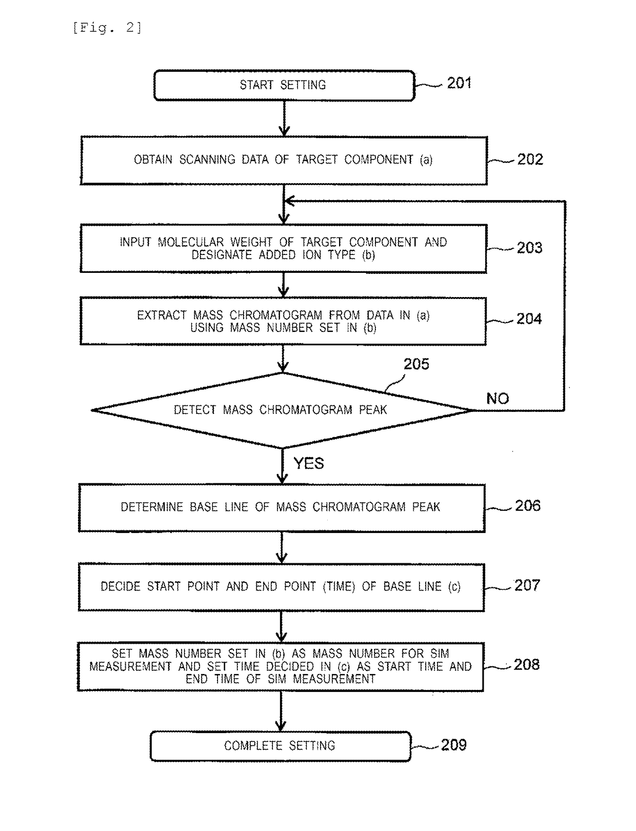
A technician is forced to determine the measurement time to be used in a selected ion monitoring (SIM) measurement while observing mass spectral data. Thus, mass spectral data and one or a plurality of mass chromatogram data items is generated on the basis of the detection results of an ion detection unit, and, for each corresponding ion component, the measurement time to be used in SIM is determined on the basis of the elution time range represented by each peak waveform of the one or plurality of mass chromatogram data items that have been generated.

Description


Claims


Application Information

Patent Timeline
Owner HITACHI HIGH-TECH CORP
Learn More