Fastener removal tool and method of using same

Active Publication Date: 2017-04-13
GENERAL ELECTRIC CO
View PDF1 Cites 0 Cited by
  • Summary
  • Abstract
  • Description
  • Claims
  • Application Information

AI Technical Summary

Benefits of technology

The patent text describes a tool for removing fastener heads from a structural surface and a method for removing fasteners from rotor assemblies. The tool includes a blade and a force transfer member that can be impulsed to move the blade from one position to another. The blade has a tip that can be used to sever the fastener head from the fastener. The technical effect of the invention is that it provides a reliable and efficient tool for removing fastener heads and fasteners from a variety of surfaces.

Problems solved by technology

However, in at least some cases, a location of the fasteners with respect to the structure as assembled increases a difficulty in accessing the fasteners to remove the fasteners.
As just one non-limiting example, at least some known rotary machines include rotor blades coupled to a rotor assembly using axially disposed twist-lock bolts, and access to the heads of the twist-lock bolts may be restricted when adjacent stages of rotor blades remain coupled to the rotor.

Method used


Image

  • Fastener removal tool and method of using same
  • Fastener removal tool and method of using same
  • Fastener removal tool and method of using same

Examples


Embodiment Construction

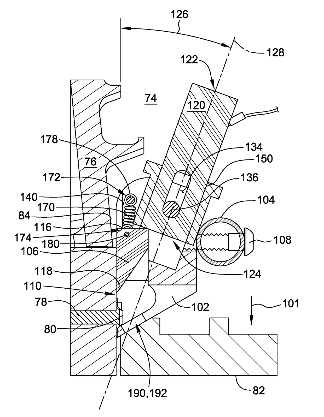
[0014]The exemplary tool and methods described herein overcomes at least some of the disadvantages associated with known fastener-removal tools. The embodiments described herein provide a body with an alignment surface configured to couple substantially flush against a surface from which the fastener head protrudes, a blade coupled to the body for movement generally parallel to the body alignment surface, and a force transfer member coupled to the body at an acute angle with respect to the blade movement direction. An impulse delivered to the force transfer member actuates the blade.

[0015]Unless otherwise indicated, approximating language, such as “generally,”“substantially,” and “about,” as used herein indicates that the term so modified may apply to only an approximate degree, as would be recognized by one of ordinary skill in the art, rather than to an absolute or perfect degree. Approximating language may be applied to modify any quantitative representation that could permissibl...


PUM

PropertyMeasurementUnit
Forceaaaaaaaaaa
Angleaaaaaaaaaa
Shapeaaaaaaaaaa

Abstract

A tool for removing a fastener head from a fastener includes a body that includes an alignment surface configured to couple substantially flush against a structural surface proximate the fastener head. A blade coupled to the body includes a tip configured to sever the fastener head from the fastener as the blade is moved in a first direction generally parallel to the alignment surface from a first blade position to a second blade position. The tool also includes a force transfer member coupled to the body for movement parallel to a longitudinal axis of the force transfer member. The longitudinal axis is oriented at an acute angle with respect to the first direction. The force transfer member is configured to move the blade from the first blade position to the second blade position in response to an impulse received by the force transfer member.

Description

BACKGROUND[0001]The field of the disclosure relates generally to tools for removing fasteners, and more particularly to a tool for severing a head from a fastener installed in a structure.[0002]At least some known structures are assembled using fasteners, such as, but not limited to, bolts, screws, and rivets. Moreover, at least some such structures require partial disassembly and, thus, removal of the fasteners, for inspection, maintenance, and / or repair. However, in at least some cases, a location of the fasteners with respect to the structure as assembled increases a difficulty in accessing the fasteners to remove the fasteners. As just one non-limiting example, at least some known rotary machines include rotor blades coupled to a rotor assembly using axially disposed twist-lock bolts, and access to the heads of the twist-lock bolts may be restricted when adjacent stages of rotor blades remain coupled to the rotor.BRIEF DESCRIPTION[0003]In one aspect, a tool for removing a fasten...

Claims


Application Information

Patent Timeline
IPC IPC(8): B25B27/14B25D3/00
CPCB25D3/00B25B27/14B23D31/00B21J15/145B21J15/50F01D5/3053F01D25/285F05D2230/80F05D2230/70Y10T29/53943Y10T29/49821
Inventor SAJDAK, LUKASZKOSZARNY, KAMILHOLMES, JAMES BRADFORD
Owner GENERAL ELECTRIC CO
Why Eureka
Try Eureka