Projector and control method for projector
- Summary
- Abstract
- Description
- Claims
- Application Information
AI Technical Summary
Benefits of technology
Problems solved by technology
Method used
Image

Examples
first embodiment
[0036]An embodiment of the invention is explained below with reference to the drawings.
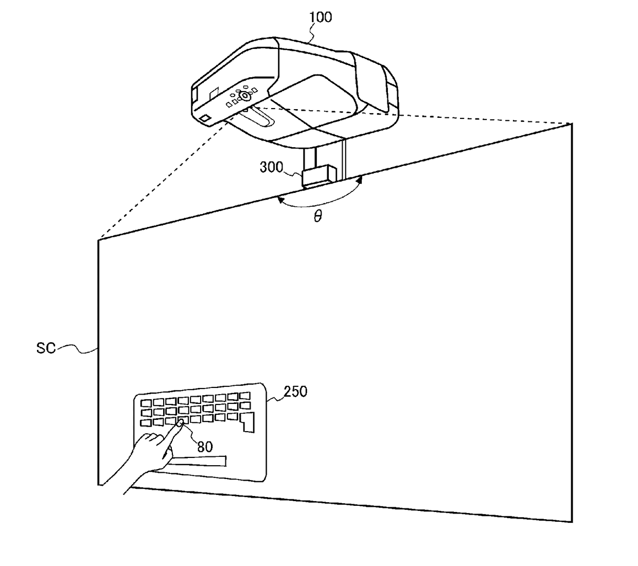
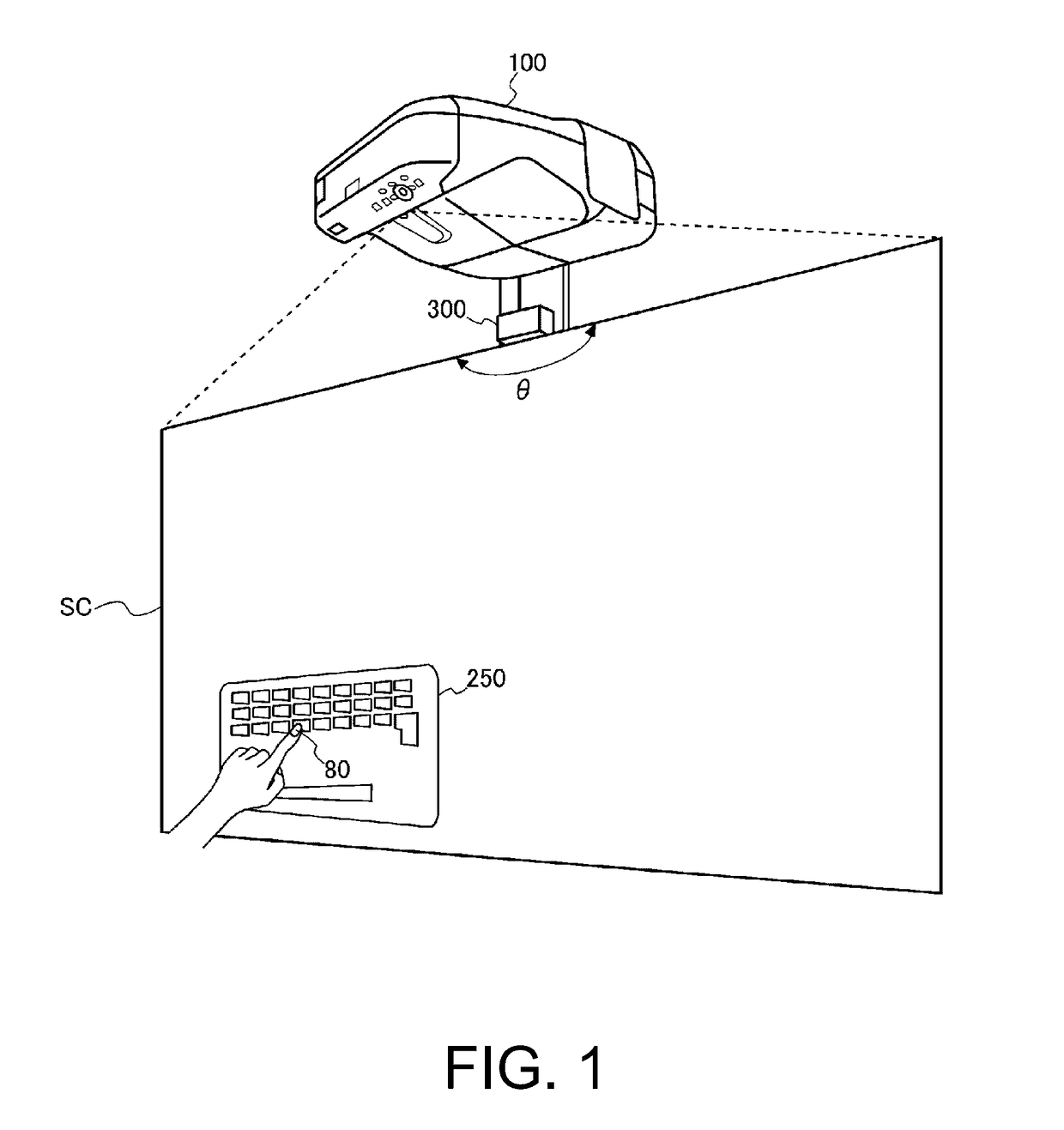
[0037]FIG. 1 is a diagram showing a setting state of a projector 100.
[0038]The projector 100 is set right above or obliquely above a screen SC (a projection surface) and projects an image onto the screen SC. In the following explanation, an image projected on the screen SC by the projector 100 is referred to as projected image and a region of the screen SC on which the projected image is displayed is referred to as projection region. The screen SC is a flat plate or a curtain fixed to a wall surface or erected on a floor surface. A wall of a meeting room or the like can also be directly used as the screen SC. In this case, the projector 100 is desirably attached to an upper part of the wall used as the screen SC.
[0039]The projector 100 detects operation by an operator on the screen SC. The projector 100 detects a pointer 80, which is a finger of the operator, and detects the operation on the scree...
second embodiment
[0132]A second embodiment of the invention is explained.
[0133]FIG. 7 is a configuration diagram showing the configuration of the projector 100 in the second embodiment (the projector 100 in the second embodiment is referred to as projector 100B).
[0134]The projector 100B in this embodiment further includes a converting section 178 in the control section 170B.
[0135]The converting section 178 functioning as a coordinate converting section converts an operation position of operation by the pointer 80 detected by the pointer detecting section 150 into coordinate information indicating a coordinate in a frame of image data. Details of processing of the converting section 178 are explained below.
[0136]An image processing section 162B in this embodiment functions as an object detecting section and develops, in the frame memory 163, input image data input from the image input section 161 and analyzes the input image data.
[0137]The image processing section 162B executes detection processing f...
third embodiment
[0183]A third embodiment of the invention is explained.
[0184]The configuration of the projector 100 in the third embodiment is the same as the configuration of the projector 100B in the second embodiment shown in FIG. 7. Therefore, detailed explanation of the configuration is omitted. The projector 100 in the third embodiment is hereinafter referred to as projector 100C.
[0185]In this embodiment, when the screen keyboard image cannot be detected in step S14 in FIG. 8, the projector 100C displays, according to a request from a user, a screen keyboard image having a size designated by the user.
[0186]FIG. 10 is a flowchart for explaining the operation of the projector 100C in this embodiment. Note that the operation in steps S11 to S19 is already explained with reference to the flowchart of FIG. 8. Therefore, detailed explanation of the operation is omitted.
[0187]The control section 170C determines according to a signal input from an image processing section 162C whether the first scree...
PUM
 Abstract
Description
Claims
Application Information
 - R&D Engineer
- R&D Manager
- IP Professional
- Industry Leading Data Capabilities
- Powerful AI technology
- Patent DNA Extraction
Browse by: Latest US Patents, China's latest patents, Technical Efficacy Thesaurus, Application Domain, Technology Topic.
© 2024 PatSnap. All rights reserved.Legal|Privacy policy|Modern Slavery Act Transparency Statement|Sitemap