
Conductive terminal and electrical connector assembly

a technology of conductive terminals and electrical connectors, which is applied in the direction of coupling contact members, coupling device connections, two-part coupling devices, etc., can solve the problems of unstable contact between easy to affect the two contact elastic pieces of the two conductive terminals, and the electrical connection of the conductive terminal is less stable, so as to promote performance and stability, save manufacturing costs, and improve the effect of reliability

Active Publication Date: 2017-04-13
MOLEX INC
View PDF8 Cites 1 Cited by
  • Summary
  • Abstract
  • Description
  • Claims
  • Application Information

AI Technical Summary

Benefits of technology

[0006]Therefore, the present disclosure provides a conductive terminal which can resolve the previous problem.
[0007]Therefore, the present disclosure further provides an electrical connector assembly which can resolve the previous problem.
[0024]The beneficial effects of the present disclosure lie in that: the conductive terminal of the first connector and the conductive terminal of the second connector are identical in structure and dimension, manufacturing cost may be saved; in every two mated conductive terminal, the two first contact portions of one conductive terminal respectively contact the two second contact portions of the other conductive terminal and the two first contact portions of the other conductive terminal respectively contact the two second contact portions of the one conductive terminal, so that four contacting regions are formed between every two mated conductive terminals, which provides a more stable and more reliable electrical connection and can promote performance and stability under long-term use; the structural design of the conductive terminal may prevent hooking and entangling between one conductive terminal and another conductive terminal or between the conductive terminal and the cable during manufacturing, and in turn prevent the conductive terminal from being damaged; and, that the two keys are respectively engaged with the two keys grooves may prevent the first connector and the second connector from being improperly inserted.

Problems solved by technology

GB886,251A, when the male connector and the female connector are mated with each other, the conductive terminal of the male connector and the conductive terminal of the female connector contact with each other via the two contact elastic pieces, there is only one contacting region between the two mated conductive terminals, but both of the two contact elastic pieces of the two conductive terminals have elasticity, therefore the two contact elastic pieces are easily affected by an improper external force, such as vibration, pulling from the cable and the like, the two contact elastic pieces of the two conductive terminals cannot stably contact with each other.
Moreover, after long-term use, the contact elastic piece may generate elastic fatigue, which also easily results in the contact between the two contact elastic pieces of the two conductive terminals not stable.
However, each conductive terminal of the above two electrical connector is used to electrically connect a wire on a circuit board, but is not used to mate with another conductive terminal, and each conductive terminal of the two electrical connectors only has one contacting region or two contacting regions, thereby also easily resulting in electrical connection of the conductive terminal less stable.

Method used


Image

  • Conductive terminal and electrical connector assembly
  • Conductive terminal and electrical connector assembly
  • Conductive terminal and electrical connector assembly

Examples


Embodiment Construction

[0051]Before the present disclosure is described in detail, it should be noted that similar element is indicated by the same reference numeral in the following description.

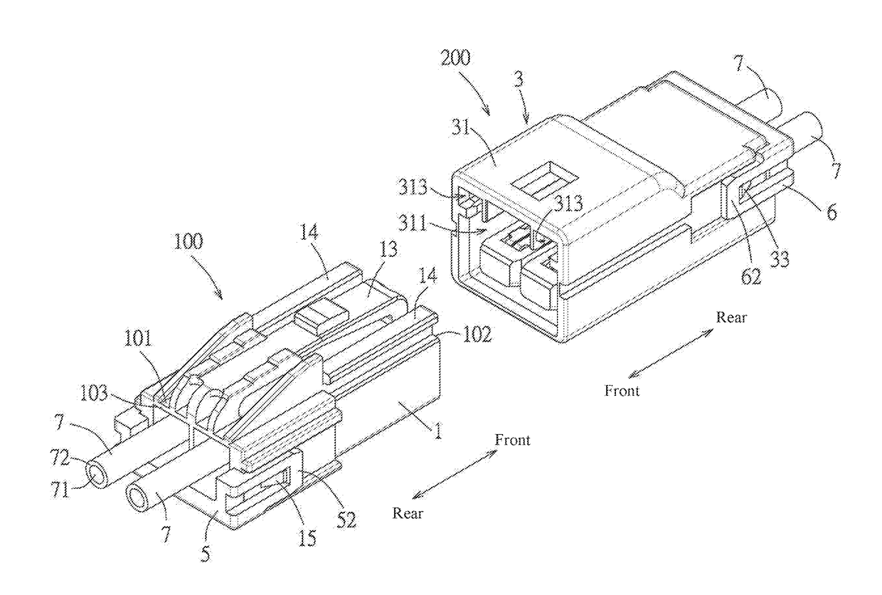
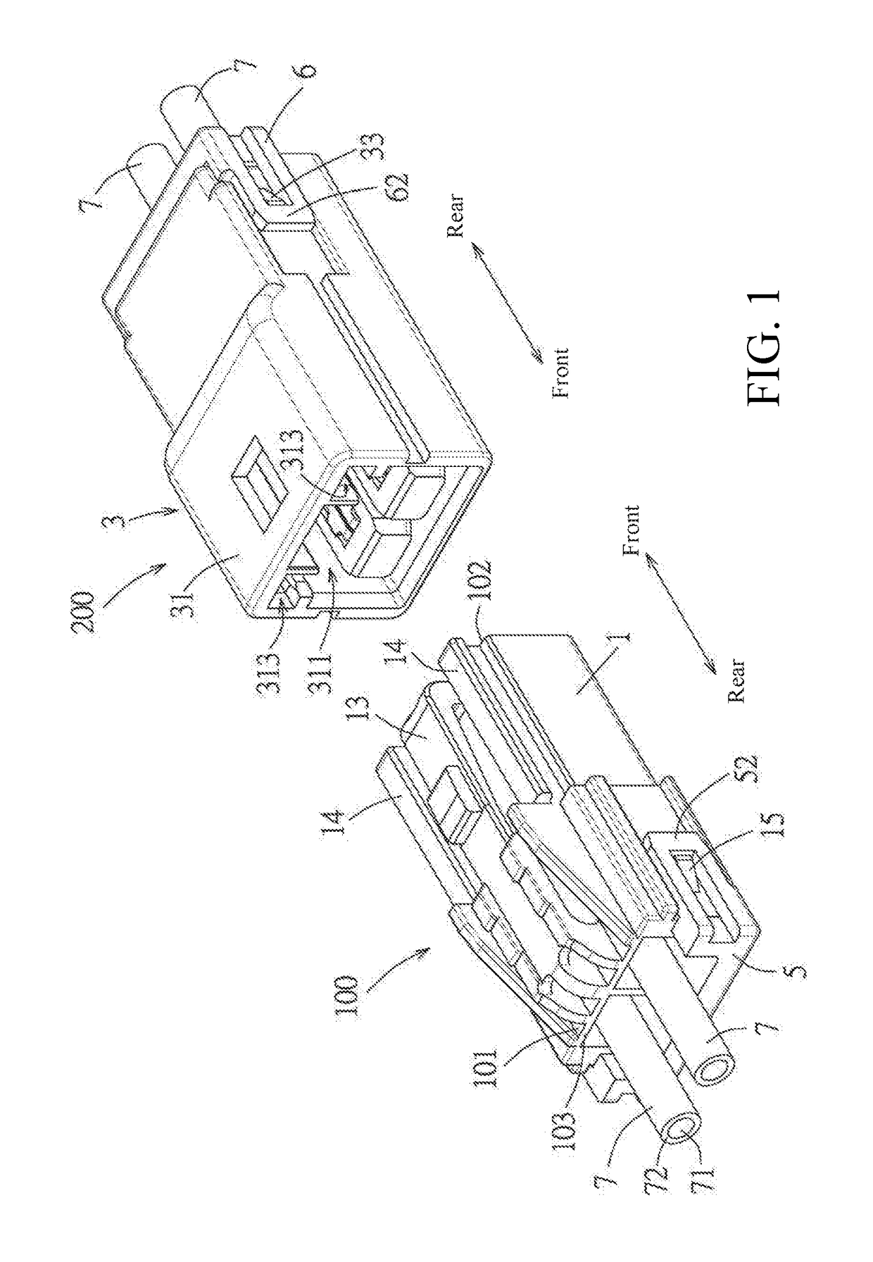
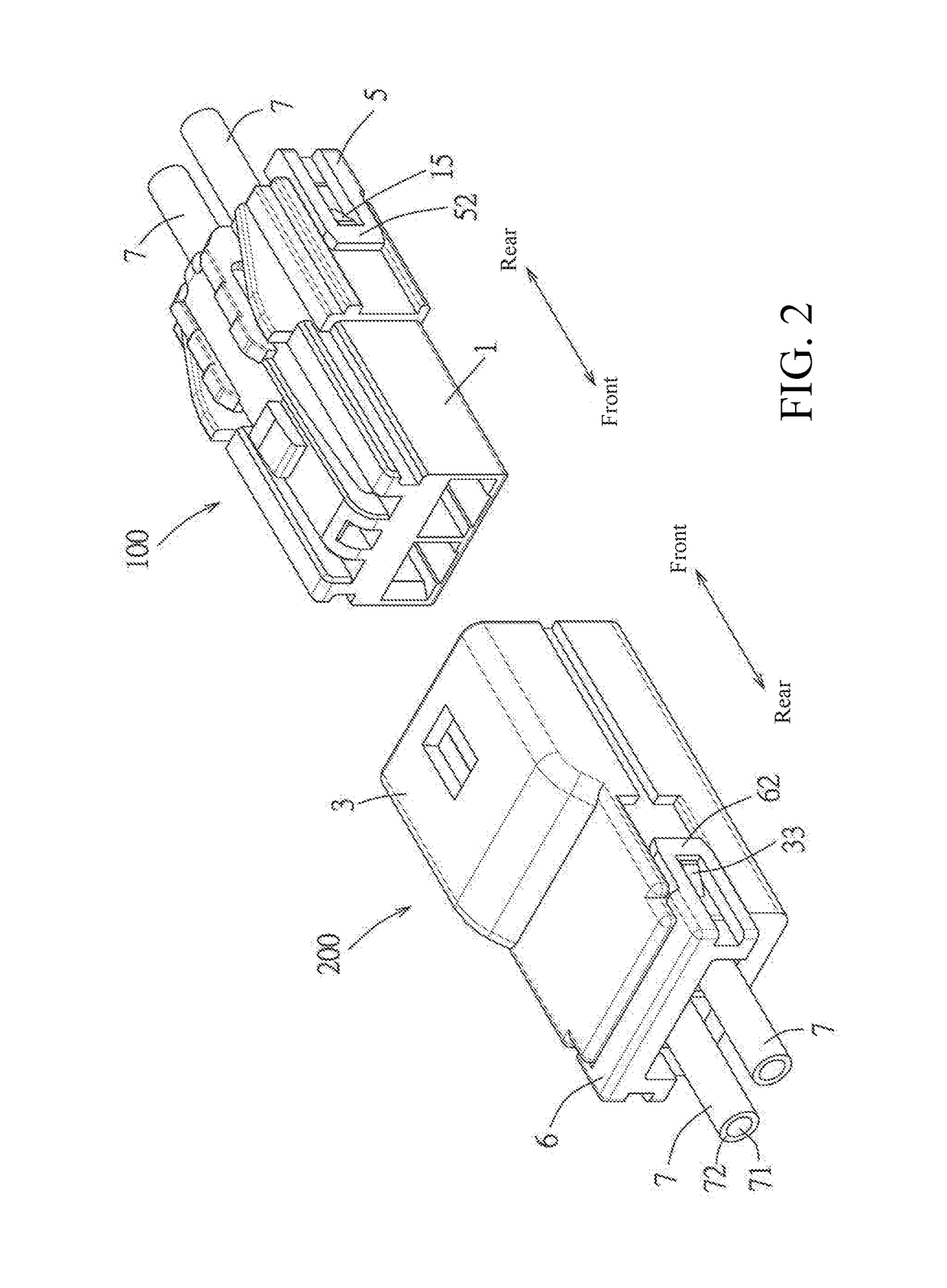
[0052]Referring to FIG. 1, FIG. 2 and FIG. 3, an embodiment of an electrical connector assembly of the present disclosure comprises: a first connector 100 and a second connector 200 which may be mated with the first connector 100. The first connector 100 comprises a first insulating housing 1, a plurality of conductive terminals 2 provided in the first insulating housing 1 and a first terminal holding member 5. The second connector 200 comprises a second insulating housing 3, a plurality of conductive terminals 2 provided in the second insulating housing 3 and a second terminal holding member 6. In the embodiment, the conductive terminal 2 of the first connector 100 and the conductive terminal 2 of the second connector 200 are identical.

[0053]Referring to FIG. 3 and FIG. 4, each conductive terminal 2 of the first ...


PUM


Abstract

A conductive terminal is provided which includes a base unit, two elastic contact pieces, a tail unit and two contact plates. The base unit includes a bottom plate extending along a front-rear direction and two side plates integrally extending upwardly from a left and right sides of the bottom plate respectively. The two elastic contact pieces are arranged side by side, each elastic contact piece comprises a connecting portion bent upwardly from a front end of the bottom plate, an arm portion extending rearwardly from the connecting portion, positioned above the bottom plate and spaced apart from the bottom plate, and a first contact portion positioned at a rear end of the arm portion. The tail unit is connected to a rear end of the bottom plate. The two contact plates are respectively bent from two upper edges of two front ends of the two side plates toward each other.

Description

RELATED APPLICATIONS[0001]This application claims priority to Chinese Application No. 201510659101.4, filed Oct. 12, 2015, which is incorporated herein by reference in its entirety.TECHNICAL FIELD[0002]The present disclosure relates to a conductive terminal and an electrical connector assembly, and more specifically relates to a conductive terminal and an electrical connector assembly in which the two conductive terminals may be mated with each other to form four contacting regions.BACKGROUND ART[0003]In a known matable male connector and female connector assembly, a conductive terminal provided in a male connector and a conductive terminal provided in a female connector each have a contact elastic piece and each are used to connect a cable, for example, as disclosed in United Kingdom patent application publication No. GB886,251A, when the male connector and the female connector are mated with each other, the conductive terminal of the male connector and the conductive terminal of t...

Claims


Application Information

Patent Timeline
Patent Type & Authority Applications(United States)
IPC IPC(8): H01R13/24H01R13/436H01R24/62
CPCH01R13/245H01R2103/00H01R13/4367H01R24/62H01R13/2492H01R13/26H01R13/28
Inventor ANG, LAY KHIMLIM, KIAN HENG
Owner MOLEX INC
Learn More