
Band clip and wire harness

Inactive Publication Date: 2017-04-20
SUMITOMO WIRING SYST LTD
View PDF14 Cites 1 Cited by
  • Summary
  • Abstract
  • Description
  • Claims
  • Application Information

AI Technical Summary

Benefits of technology

The present invention provides a band clip and a wire harness that can be easily removed from a vehicle body panel. The band clip includes a binding band that binds a group of wires, and a clip portion that is integrally provided with the binding band and locking in a through hole of the vehicle body panel. The clip portion includes a flange portion that abuts the vehicle body panel without passing through the through hole, an inclined piece that passes through the through hole and is locked in the through hole, and a connecting piece that connects the clip portion to the vehicle body panel, which can contract to decrease the size of the clip to facilitate its removal from the through hole. The wire harness includes the band clip and other components that can be easily removed from the vehicle body panel. Overall, the invention improves the workability of removing the band clip and wire harness from the vehicle body panel.

Problems solved by technology

Cutting the column portion of the clip portion negatively impacts workability, causing damage or destruction of the band clip.
Thus, this type of band clip does not meet an environmentally conscious requirement of being recycleable / reusable, as required of automobile parts in recent years.

Method used


Image

  • Band clip and wire harness
  • Band clip and wire harness
  • Band clip and wire harness

Examples


Embodiment Construction

[0026]The particulars shown herein are by way of example and for purposes of illustrative discussion of the embodiments of the present invention only and are presented in the cause of providing what is believed to be the most useful and readily understood description of the principles and conceptual aspects of the present invention. In this regard, no attempt is made to show structural details of the present invention in more detail than is necessary for the fundamental understanding of the present invention, the description taken with the drawings making apparent to those skilled in the art how the forms of the present invention may be embodied in practice.

[0027]In the following, an embodiment of the present invention is described with reference to the drawings.

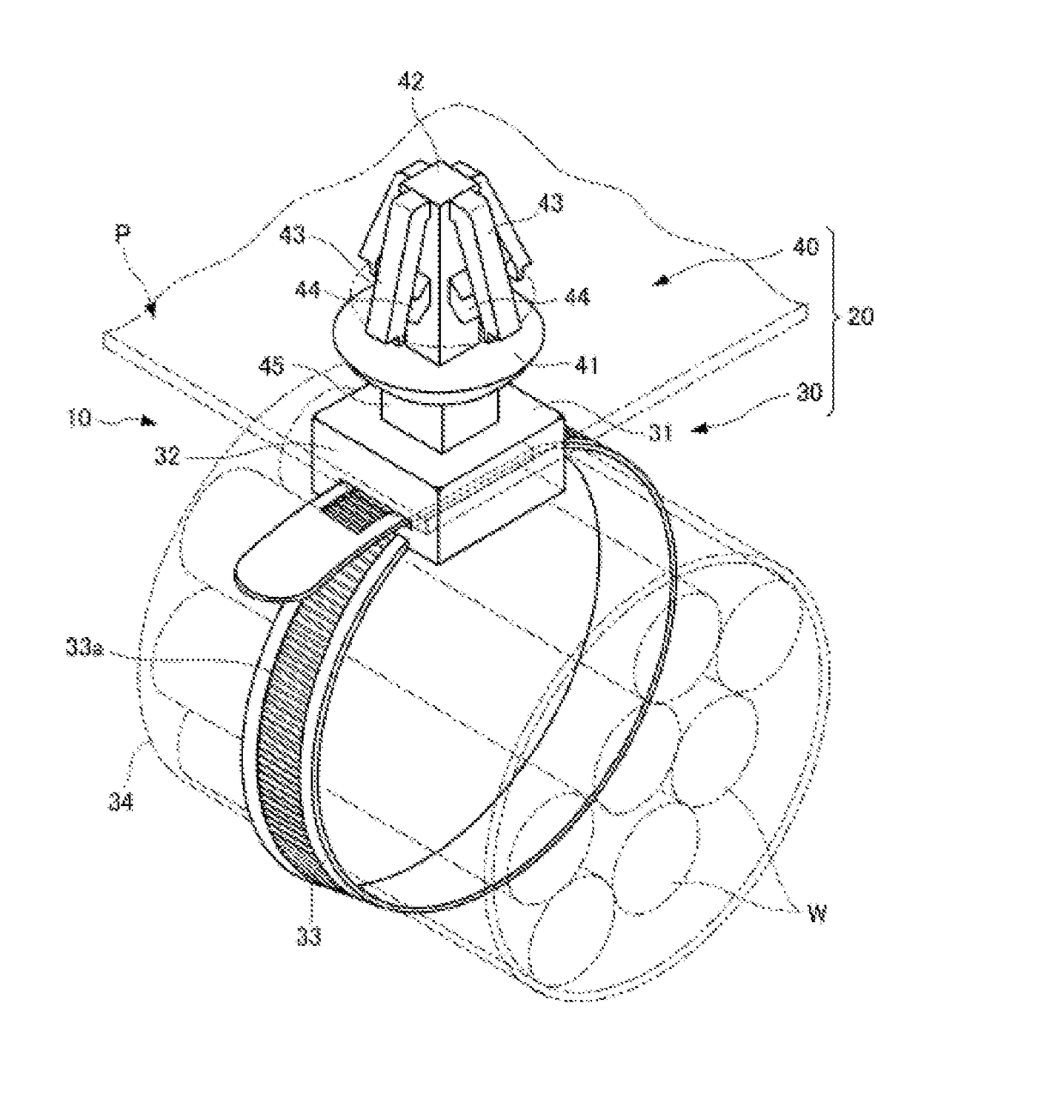
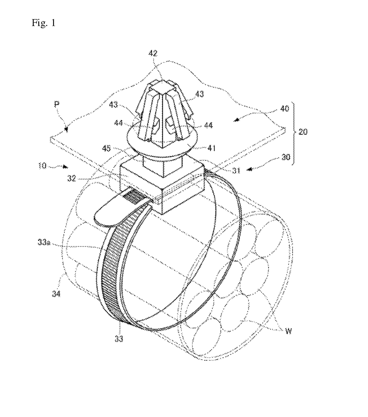
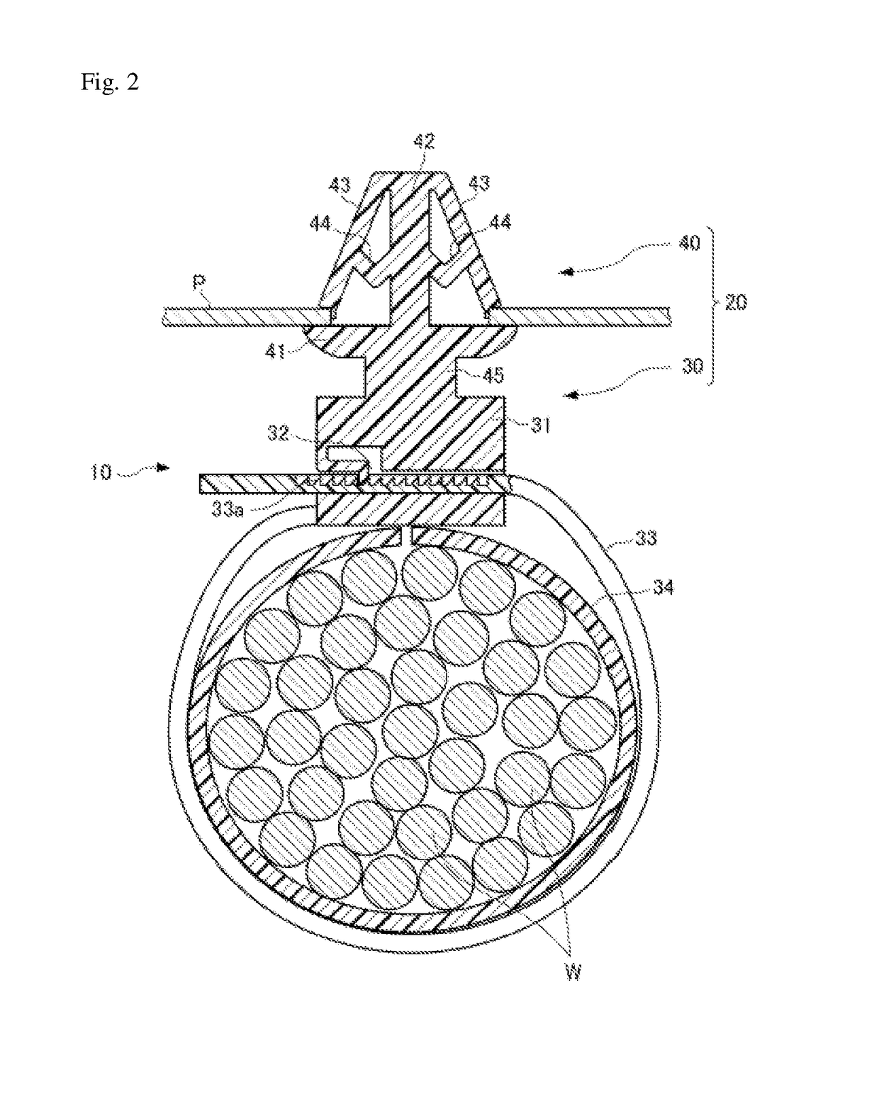
[0028]FIGS. 1 and 2 illustrate a band clip and a wire harness according to an embodiment of the present invention.

[0029]FIG. 1 is a perspective view of a wire harness 10 according to the present embodiment, and FIG. 2 is a l...


PUM


Abstract

A band clip includes a binding band portion and a clip portion. The clip portion has a flange portion, a column portion, four inclined pieces inclined relative to the column portion, and a connecting piece connecting the column portion and each inclined piece. The clip portion is constituted of a shape memory resin and acquires a memorized shape such that a connecting distance between the column portion and each inclined piece becomes shorter than at normal temperature. When fitting the clip portion to a through hole, a second end portion near a vehicle body panel bends so that the inclined piece is locked to an edge of the through hole. When removing the clip portion from the through hole, a distance between a lower end portion of the inclined piece and a central axis of the column portion reaches a size that can pass through the through hole.

Description

CROSS-REFERENCE TO RELATED APPLICATIONS[0001]The present application claims priority under 35 U.S.C. §119 of Japanese Application No. 2015-202863, filed on Oct. 14, 2015, the disclosure of which is expressly incorporated by reference herein in its entirety.BACKGROUND OF THE INVENTION[0002]1. Field of the Invention[0003]The present invention relates to a band clip locking to a vehicle body and a wire harness provided with the band clip.[0004]2. Description of Related Art[0005]Traditionally, a band clip that locks a group of electrical wires in a through hole of a vehicle body panel or the like includes a binding band portion that binds the group of electrical wires, and a clip portion that is integrally provided on a head of the binding band portion and is locked in the through hole of the vehicle body panel.[0006]The clip portion includes a flange portion provided integrally with the head at a position separated from the head by a required distance, the flange portion abutting the v...

Claims


Application Information

Patent Timeline
IPC IPC(8): B60R16/02B65D63/10
CPCB60R16/0215B65D2563/108B65D63/1027
Inventor WAKABAYASHI, MASATAKAFUKUDA, MINORU
Owner SUMITOMO WIRING SYST LTD
Learn More