Bicycle and control method thereof

a technology of cleat pedals and shoes, applied in the field of bicycles, can solve the problems of difficult for the rider to maintain an effective pedaling posture, the rider's feet slip easily, and the rider's shoes are difficult to match and couple the coupling protrusion of the shoe to the coupling groove of the pedal, so as to achieve convenient and safe coupling between the shoe and the pedal

Inactive Publication Date: 2017-04-20
HL MANDO CORP
View PDF0 Cites 18 Cited by
  • Summary
  • Abstract
  • Description
  • Claims
  • Application Information

AI Technical Summary

Benefits of technology

[0011]Therefore, it is an aspect of the present invention to provide a bicycle capable of conveniently and safely coupling a rider's shoe and a cleat pedal and releasing from the coupling.
[0018]The bicycle may further include a speed sensor configured to sense a speed of the bicycle, wherein the electromagnetic including a plurality of electromagnets may be provided at the pedal body, and the electronic control unit may control operation of the switching unit so that as the sensed bicycle speed is decreased, the number of the electromagnet to which power is supplied among the plurality of electromagnets is decreased.

Problems solved by technology

In general, while a bicycle is traveling, since the rider's feet are not fixed to the bicycle's pedals, the rider's feet slip easily, and since his or her knees are together, it is difficult for the rider to maintain an effective pedaling posture.
However, because of a characteristic that the bottom of a shoe is not seen, conventionally, it is difficult for the rider to match and couple the coupling protrusion of the shoe to the coupling groove of the pedal.
In addition, since the shoe is turned at a predetermined angle and the coupling protrusion of the shoe is withdrawn from the coupling groove of the pedal when the coupling is released, when a rider rides the bicycle for a long time, the rider may forget that the shoe is coupled to the cleat pedal when stopping, or suddenly stopping due to something unexpected happening, and the rider may fall down and become injured when the rider cannot withdraw the shoe from the pedal.

Method used


Image

  • Bicycle and control method thereof
  • Bicycle and control method thereof
  • Bicycle and control method thereof

Examples


Embodiment Construction

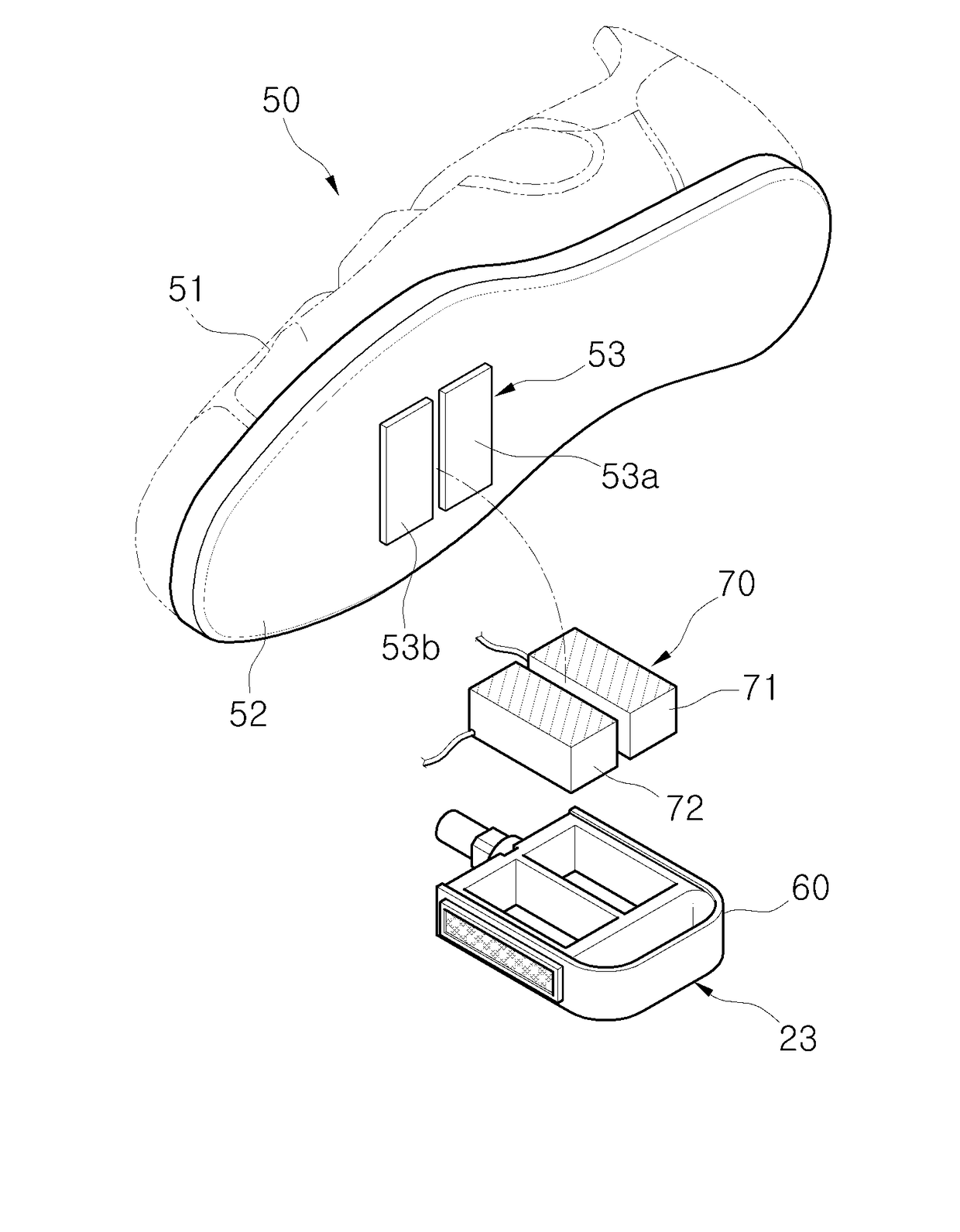
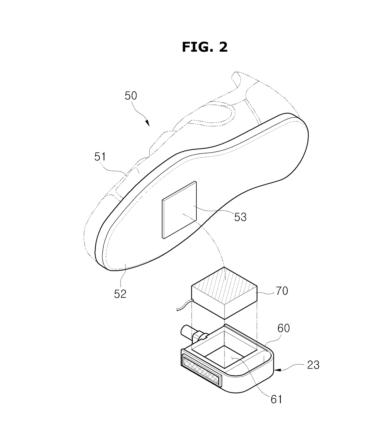
[0031]Hereinafter, embodiments of the present invention will be described in detail with reference to following drawings. The following drawings are examples to provide the scope of the present invention to those skilled in the art. The present invention is not limited to the following embodiments and may be implemented in different forms. Parts irrelevant to description are omitted in the drawings in order to clearly describe the present invention, and widths, lengths, thicknesses of components in the drawings may be exaggerated for convenience of description. In this specification, like reference characters denote like components.

[0032]In the embodiments, a chainless electric bicycle is described as an example, however, they are not limited thereto, the embodiments of the present invention may be applied to an electric bicycle or a general bicycle by suitable modifications and variations.

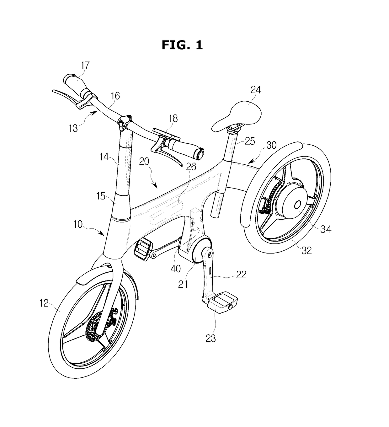
[0033]FIG. 1 is a block diagram illustrating an electric bicycle according to one embodiment o...


PUM

PropertyMeasurementUnit
speedaaaaaaaaaa
magnetic forceaaaaaaaaaa
poweraaaaaaaaaa

Abstract

Disclosed herein are a bicycle and a control method of the same. The bicycle includes an electromagnet installed in a pedal body rotatably coupled to a pedal shaft and configured to generate a magnetic force when power is supplied thereto, a switching unit configured to switch on or off the power supplied to the electromagnet, and an electronic control unit configured to turn on or off the switching unit.

Description

CROSS-REFERENCE TO RELATED APPLICATION[0001]This application claims the benefit of Korean Patent Application No. 2015-0145905, filed on Oct. 20, 2015 in the Korean Intellectual Property Office, the disclosure of which is incorporated herein by reference.BACKGROUND[0002]1. Field[0003]Embodiments of the present invention relate to a bicycle and a control method of the same, and more particularly, to a bicycle including a cleat pedal which is coupled to a rider's shoes for effective pedaling and a control method of the same.[0004]2. Description of the Related Art[0005]In general, while a bicycle is traveling, since the rider's feet are not fixed to the bicycle's pedals, the rider's feet slip easily, and since his or her knees are together, it is difficult for the rider to maintain an effective pedaling posture.[0006]Recently, a cleat pedal which is fixed to a rider's shoe has been used to prevent slippage from the pedal and to use a force effectively when pedaling.[0007]Since such a cl...

Claims


Application Information

Patent Timeline
Patent Type & Authority Applications(United States)
IPC IPC(8): B62M3/08H01F7/06
CPCH01F7/064B62M3/086A43B3/00A43B13/00B62M3/08B62M3/16B62M6/80B62M6/50B62M6/65B62M19/00A43B5/14A43B13/10A43B1/0054A43B5/00
Inventor PAICK, IN-HA
Owner HL MANDO CORP
Why Eureka
Try Eureka