High-frequency module

a technology of high-frequency modules and directional couplers, which is applied in the association of printed circuit non-printed electric components, waveguide type devices, multiple-port networks, etc., can solve the problems of difficult to readjust the characteristics of directional couplers 501, etc., and achieves the effect of reducing the number of components, making them cheaper, smaller, and easy to adjus

Active Publication Date: 2017-04-20
MURATA MFG CO LTD
View PDF7 Cites 2 Cited by
  • Summary
  • Abstract
  • Description
  • Claims
  • Application Information

AI Technical Summary

Benefits of technology

[0007]Preferred embodiments of the present invention provide a high-frequency module including a multilayer substrate defining a directional coupler that significantly reduces or prevents interference with other high-frequency circuit elements and whose characteristics are easily adjusted.

Problems solved by technology

Furthermore, because the directional coupler 501 is provided within the multilayer substrate 500, it is difficult to readjust the characteristics of the directional coupler 501 in the case where those characteristics have changed.

Method used


Image

  • High-frequency module
  • High-frequency module
  • High-frequency module

Examples


Embodiment Construction

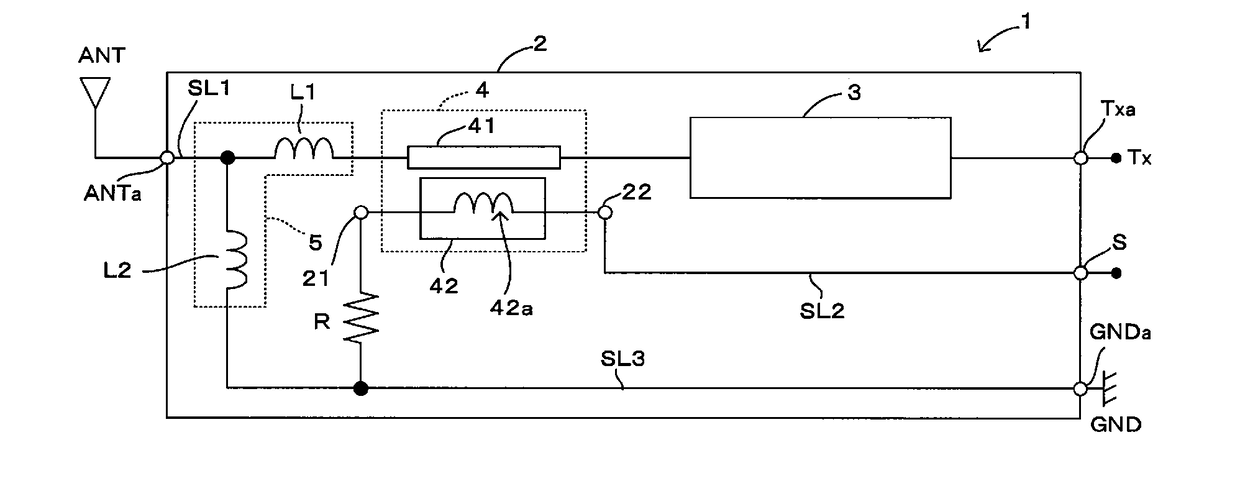
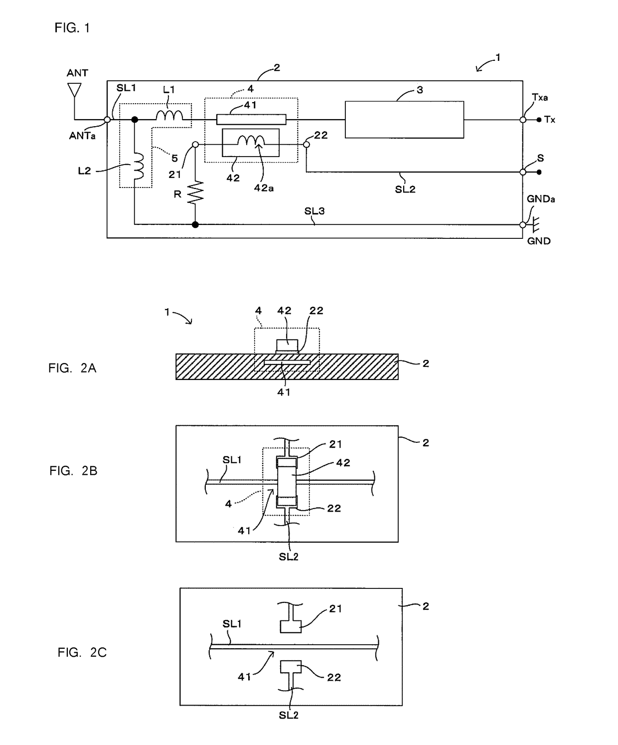
[0032]A high-frequency module according to a preferred embodiment of the present invention will be described with reference to FIGS. 1 and 2A-2C.

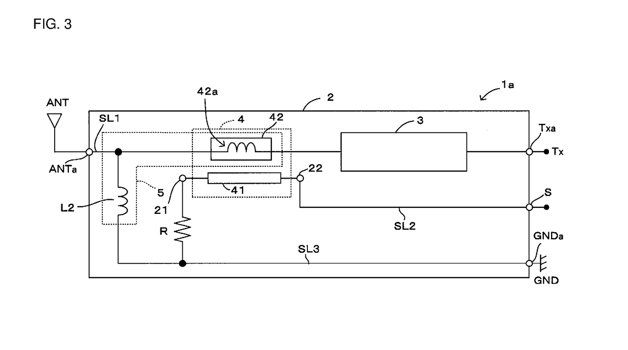
[0033]Note that FIGS. 1 and 2A-2C illustrate a primary configuration of a preferred embodiment of the present invention, and other components such as signal paths, high-frequency circuit elements, and so on are not shown in order to simplify the descriptions. Like FIG. 1, FIG. 3, which is referred to in another preferred embodiment that will be described later, also illustrates only the primary configuration for the same reason.

[0034]A high-frequency module 1 illustrated in FIG. 1 is installed in a motherboard or the like of a mobile communication terminal having communication functionality, such as a cellular phone or a mobile information terminal, and is used as what is known as a front-end module disposed immediately subsequent to an antenna element ANT. In this preferred embodiment, the high-frequency module 1 includes a multilayer subs...


PUM


Abstract

An inductor component is disposed outside a multilayer substrate, and thus a directional coupler defined by an internal wiring electrode and a coil electrode within the inductor component that is mounted on a pair of land electrodes, the multilayer substrate significantly reduces or prevents interference with other high-frequency circuit elements disposed in or on the multilayer substrate. Additionally, if a plurality of inductor components having different inductor characteristics are prepared, a high-frequency module including the multilayer substrate capable of defining the directional coupler whose characteristics are able to adjusted with ease is able to be provided simply by selecting the desired inductor component from the inductor components and replacing that inductor component.

Description

CROSS REFERENCE TO RELATED APPLICATIONS[0001]This application claims the benefit of priority to Japanese Patent Application No. 2014-142121 filed on Jul. 10, 2014 and is a Continuation application of PCT Application No. PCT / JP2015 / 069837 filed on Jul. 10, 2015. The entire contents of each application are hereby incorporated herein by reference.BACKGROUND OF THE INVENTION[0002]1. Field of the Invention[0003]The present invention relates to a high-frequency module including a multilayer substrate in or on which are provided a first signal path through which an RF signal passes and a second signal path through which an RF signal passes.[0004]2. Description of the Related Art[0005]Thus far, a high-frequency module including high-frequency circuit elements such as switch circuits, duplexers, directional couplers, and the like has been provided. Such a high-frequency module is used as a front-end module connected immediately subsequent to an antenna element, and includes a multilayer subs...

Claims


Application Information

Patent Timeline
Patent Type & Authority Applications(United States)
IPC IPC(8): H01P5/18H04B1/04H05K1/11H03H7/38H05K1/02H05K1/18
CPCH01P5/18H05K1/0243H04B1/04H05K1/115H03H7/38H05K1/181H01P5/184H01P5/187H05K2201/09772H05K2201/1003
Inventor HANAOKA, KUNITOSHI
Owner MURATA MFG CO LTD
Why Eureka
Try Eureka