Relays in telecommunications networks

a technology of telecommunications networks and relays, applied in the direction of transmission path division, repeater circuits, line-transmission details, etc., can solve the problems of interference affecting the data rate, node cannot simultaneously transmit and receive, and transmission over such wireless uplink and downlink channels is subject to errors, so as to reduce or prevent interference

Active Publication Date: 2010-11-25
VODAFONE IP LICENSING
View PDF3 Cites 44 Cited by
  • Summary
  • Abstract
  • Description
  • Claims
  • Application Information

AI Technical Summary

Benefits of technology

[0027]In this aspect of the system described herein, rather than allowing multiple relays to communicate with a mobile device, the system selects one relay for communication with the mobile device. This reduces or prevents interference that would otherwise be experienced by the mobile device.
[0028]The first relay node may be muted for the duration of the transmission of the transmission resource element to the at least one of said mobile terminals. When the selected relay is communicating with the mobile device using a resource element all other relays in range of the mobile device are muted for that resource element to prevent interference.

Problems solved by technology

Transmissions over such wireless uplink and downlink channels are subject to errors, for example due to receiver noise and unpredictable interference variations.
At present, typically only those mobile terminals that are in close proximity to a base station (eNB) can achieve a high data rate, as interference affects the data rate as the distance between the base station and the user terminal increases.
A further problem for LTE networks is that since LTE needs to be compatible with both LTE compatible terminals and legacy terminals (such as Rel-8 terminals to which relays are transparent), there is a challenge to integrate relays in such a network environment without unduly increasing network signalling.
Whilst such a relay system can greatly increase the data throughput, an inherent problem with relay nodes (RN) is that in most situations, a given node cannot simultaneously transmit and receive at the same frequency band, due to the transmitting and receiving antennas not being well separated.
Therefore each RN is not able to listen while transmitting, and vice versa, which introduces restrictions on their operation.
The use of relays can undesirably cause communication resource waste due to the potential for relay nodes to interfere with each other.

Method used


Image

  • Relays in telecommunications networks
  • Relays in telecommunications networks
  • Relays in telecommunications networks

Examples


Embodiment Construction

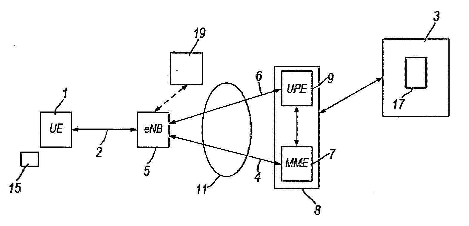
[0044]FIG. 1 shows schematically the logical elements of an LTE / SAE mobile telecommunications network. Mobile terminal (UE) 1 is registered with mobile telecommunications network core 3. The mobile terminal 1 may be any device with mobile communication capabilities, including a handheld mobile telephone, a personal digital assistant (PDA) a laptop or desktop personal computer—for example, equipped with a wireless datacard. Although only one mobile terminal 1 is shown in FIG. 1, there will in practice be a multiplicity of mobile terminals, each of which is registered with the network core 3.

[0045]The terminal 1 communicates wirelessly with the mobile telecommunications network core 3 via the radio access network (RAN) of the mobile telecommunications network core 3 over radio interface 2. The RAN comprises a plurality of eNodeBs (eNB) 5. Each eNodeB 5 performs functions generally similar to those performed by the NodeB and the radio network controller (RNC) of a 3G network. Each eNod...


PUM


Abstract

In a telecommunications network including a plurality of mobile terminals in communication with a network base station, and a plurality of relay nodes configured to assist the base station with data transmissions between the base station and one or more of said plurality of mobile terminals, a method of enabling communication resource reuse amongst the plurality of said relay nodes, the method comprising: predefining a plurality of communication resource sets, each resource set comprising one or more communication resource elements, the communication resource sets arranged so that each relay node can receive data in a predefined receiving resource set and transmit data in a predefined transmission resource set; determining which of two or more relay nodes are spatially separated from one another; and configuring at least two of the two or more spatially separated relay nodes to use the same communication resource sets.

Description

TECHNICAL FIELD[0001]The present invention relates to increasing the efficiency of relays in telecommunications networks. More particularly the present invention relates to scheduling schemes for relays in telecommunications networks, particularly LTE / SAE networks.BACKGROUND[0002]Relays are used in telecommunications networks to not only forward signals between mobile terminals and the core network, but to add power to the signal. An equivalent term for a relay is a repeater. These are employed in various types of telecommunication systems, including the Long Term Evolution (LTE) / System Architecture Evolution (SAE) currently being developed by the “3rd Generation Partnership Project” (3GPP). In this regard, Long Term Evolution (LTE) is an advanced version of UMTS that uses E-UTRA (Evolved Universal Terrestrial Radio Access), and which employs OFDMA (Orthogonal Frequency Division Multiple Access) on the downlink and SC-FDMA (Single Carrier Frequency Division Multiple Access) on the u...

Claims


Application Information

Patent Timeline
Patent Type & Authority Applications(United States)
IPC IPC(8): H04B7/14
CPCH04B7/2606H04L1/1812H04L5/0007H04W84/047H04L5/0035H04L2001/0097H04W72/1263H04L5/0032
Inventor NAN, MINGKAI
Owner VODAFONE IP LICENSING
Why Eureka
Try Eureka