Radio wall switch

a radio wall switch and switch technology, applied in the field of light and environmental control systems, devices and methods, can solve the problems of large number of electronic devices, and difficulty in reconfiguring or retrofitting, and achieve the effect of reducing or preventing interferen

Active Publication Date: 2007-09-25
THE WATT STOPPER
View PDF74 Cites 43 Cited by
  • Summary
  • Abstract
  • Description
  • Claims
  • Application Information

AI Technical Summary

Benefits of technology

[0014]In accordance with the embodiments of the invention, the radio control board is electrically coupled to the load control circuit while being positioned outside of, or external to, the wall receptacle. Positioning the radio control board with the transducer and the antenna outside of, or external to, the wall receptacle reduces or prevents interference by the receptacle box during the transmission and reception of radio signals.

Problems solved by technology

Such systems are installed during the construction of a building and are extremely difficult to reconfigure or retrofit after the construction of the building is complete.
Further, such hardwired systems are not capable of supporting complex operations where, for example, electronic devices in the same space, or in a different space, need to operate collectively.
One of the shortcomings of these prior art wireless systems, such as described by Mosebrook et al., is that they generally do not support the bandwidth required to operate and control complex arrangements and large numbers of electronic devices, such as can be required in large buildings or complexes.
Further, these prior art wireless systems are not easily programmed or reconfigured and usually require a professional to install them.
Also, these prior art wireless systems can suffer from poor reception and weak transmission of the radio control signals and, therefore, can require that the communicating electronic devices are in a preferred orientation and / or in close proximity with one another in order to function properly.

Method used


Image

  • Radio wall switch
  • Radio wall switch
  • Radio wall switch

Examples


Embodiment Construction

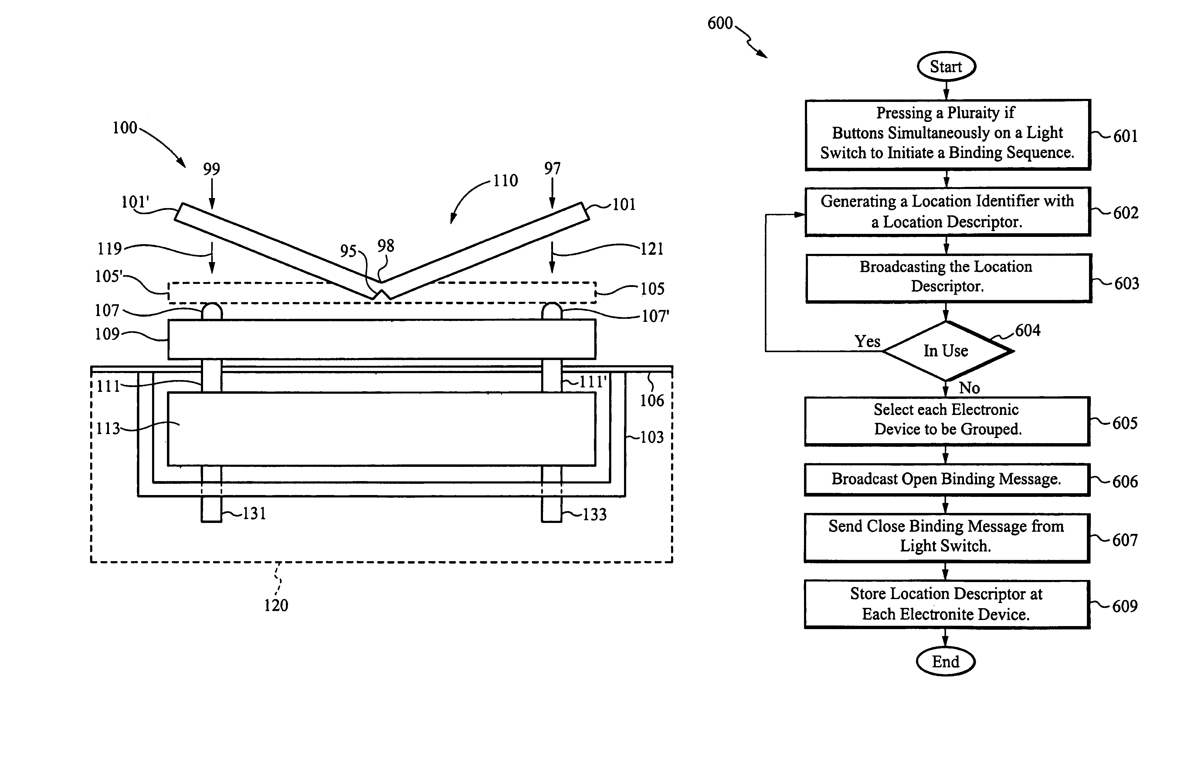
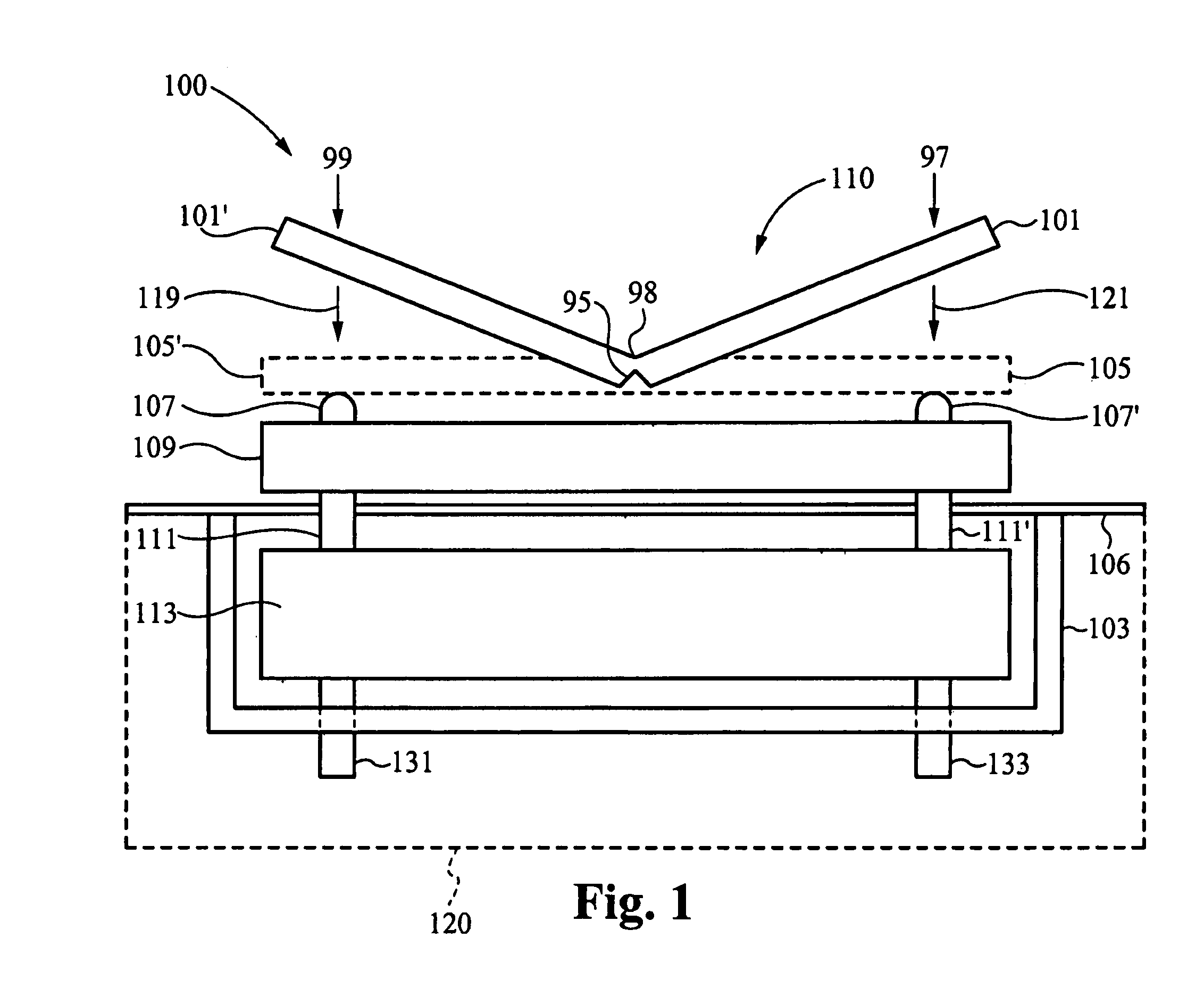
[0024]The present invention is directed to a radio wall switch that is configured to program or commission devices, such as outlets, switches, lights with or more Location Descriptors such that the electronic devices can respond to the same radio control signals. The Location Descriptors preferably correspond to the physical locations of the electronic devices, such as determined by a floor plan. The methods of programming or commissioning electronic devices is referred to herein as grouping or binding electronic devices and is also referred to as Location-based Addressing are described in U.S. patent application Ser. No. 10 / 934,222, filed Sep. 3, 2004, titled “LOCATION-BASED ADDRESSING LIGHTING AND ENVIRONMENTAL CONTROL SYSTEM, DEVICES AND METHOD,” referenced previously. Pursuant to such commissioning, programming, grouping or binding of the electronic devices, the electronic devices can be operated, and can inter-operate, by messages directed to spatial locations or addresses, rat...


PUM

PropertyMeasurementUnit
frequenciesaaaaaaaaaa
flexibleaaaaaaaaaa
resilientaaaaaaaaaa

Abstract

A radio wall switch that uses radio signals to control a load through a load circuit is disclosed. The radio wall switch is also configured group or bind electronic devices to operate collectively by responding to the same radio control signals. Preferably, the radio wall switch and electronic devices are grouped or bound to reflect their location in a floor plan architecture. The radio wall switch includes a radio control board is configured to be removable and located outside of a wall receptacle while electrically coupled to the load circuit. The radio control board includes contact switches that are selectively depressed by a switch plate for manually controlling the load. The switch plate is flexible and can be deformed to simultaneously actuate multiple contact switches to place the radio wall switch in a program mode for grouping or binding the other electronic devices.

Description

RELATED APPLICATIONS[0001]This application is a Continuation-in-part application of the co-pending U.S. patent application Ser. No. 10 / 934,222, filed on Sep. 3, 2004 and titled “LOCATION-BASED ADDRESSING LIGHTING AND ENVIRONMENTAL CONTROL SYSTEM, DEVICES AND METHOD”, which claims priority under 35 U.S.C. § 119(e) from the Co-pending U.S. Provisional Patent Application Ser. No. 60 / 500,640, filed on Sep. 5, 2003, and titled “LOCATION-BASED ADDRESSING LIGHTING AND ENVIRONMENTAL CONTROL SYSTEM, DEVICE AND METHOD.” This application also claims priority under 35 U.S.C. § 119(e) from the Co-pending U.S. Provisional Patent Application Ser. No. 60 / 625,370, filed on Nov. 5, 2004, and titled “RADIO WALL SWITCH.” The U.S. patent application Ser. No. 10 / 934,222, filed on Sep. 3, 2004 and titled “LOCATION-BASED ADDRESSING LIGHTING AND ENVIRONMENTAL CONTROL SYSTEM, DEVICES AND METHOD”; the Provisional Patent Application Ser. No. 60 / 500,640, filed on Sep. 5, 2003, and titled “LOCATION-BASED ADDRESS...

Claims


Application Information

Patent Timeline
Patent Type & Authority Patents(United States)
IPC IPC(8): H01B1/24H01H19/14
CPCH01B1/24H01H19/14H01H2300/03H01Q1/24Y02B90/20Y04S20/14
Inventor VIOLA, ROARDEBEVER, BETRANDNISHI, ROYWEIDMAN, LOIUA
Owner THE WATT STOPPER
Why Eureka
Try Eureka