Apparatus and method for low latency switching

a low-latency, data-switching technology, applied in the field of network data-switching, can solve the problems of difficult to implement layer 2 features in a serial stream at the frequencies involved, and the switch requires relatively complex circuitry,

Active Publication Date: 2017-04-20
ARISTA NETWORKS
View PDF3 Cites 16 Cited by
  • Summary
  • Abstract
  • Description
  • Claims
  • Application Information

AI Technical Summary

Benefits of technology

[0029]Some embodiments of the present invention may thus effectively involve optimising for improved low latency and / or improved determinism (fewer MAC collisions), through the abandonment of optimising bandwidth usage. By using the broadcast functionality of a crosspoint switch to distribute data to more than one receiver, the aggregate bandwidth possible is reduced and individual hardware elements' data throughput is not necessarily maximised, however the present invention recognises that the parallel processing of those multiple identical data streams has other beneficial effects. The present invention thus recognises that many existing switches are designed in order to optimise bandwidth and flexibility of use amongst many use cases, but that this is at the expense of latency and determinism.
[0089]In some embodiments of the fifth to eighth aspects of the invention, the higher layer function may additionally or alternatively comprise the ability to inject a packet into an interface MAC (media access controller), with the output of the MAC being passed to the physical layer. That is, in such embodiments user software may communicate a packet to the switch via a management interface, and the higher layer function may involve injecting the packet into either the receive or transmit MAC for a specified interface. The packet will then be transmitted on the wire from an interface. The packet may alternatively be created by software or hardware (e.g. FPGA) on the device, i.e. originating on the device instead of being communicated over the management interface. Some such embodiments may inject a packet or packets in order to subscribe to multicast on behalf of downstream hosts, for example, in accordance with the Internet Group Management Protocol Version 2 (IGMP) the subject of the Internet Society RFC2236, and / or in accordance with a protocol-independent multicast (PIM) routing protocol, and / or in accordance with a border gateway protocol (BGP), or the like. In the case of IGMP, subscribing or unsubscribing to a multicast group may comprise injecting IGMP packets for transmission to a neighbouring multicast router to register in a multicast group to receive multicast packets on behalf of downstream clients connected to the ports of the switch of the present invention, thereby obviating the need to have a downstream host perform this function.

Problems solved by technology

This approach is based on the principle of optimising bandwidth usage, but requires relatively complex circuitry within the switch.
Converting data from layer 1 to layer 2 requires data deserialization into a parallel stream because it is difficult to implement layer 2 features in a serial stream at the frequencies involved.
This means that any layer 2 processing is much slower than layer 1, and layer 2 address checking introduces a significant delay of approximately 200-400 ns for even the fastest layer 2 network switches.
When used for upstream aggregation of multiple traders' data traffic into a single stream, this requires use of a many-to-one switch such as an Ethernet switch in addition to a MetaConnect C16 switch from Metamako LP, undesirably increasing latency.
Moreover, network switches must often deal with both upstream and downstream data paths in a single device, complicating the signal paths and introducing clocking limitations.

Method used


Image

  • Apparatus and method for low latency switching
  • Apparatus and method for low latency switching
  • Apparatus and method for low latency switching

Examples


Embodiment Construction

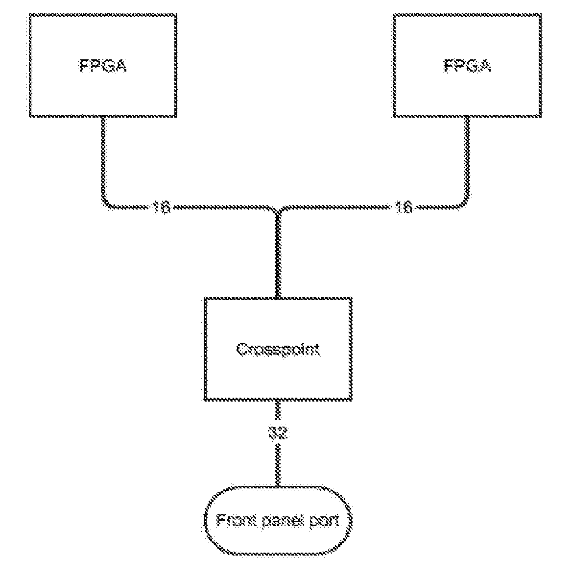
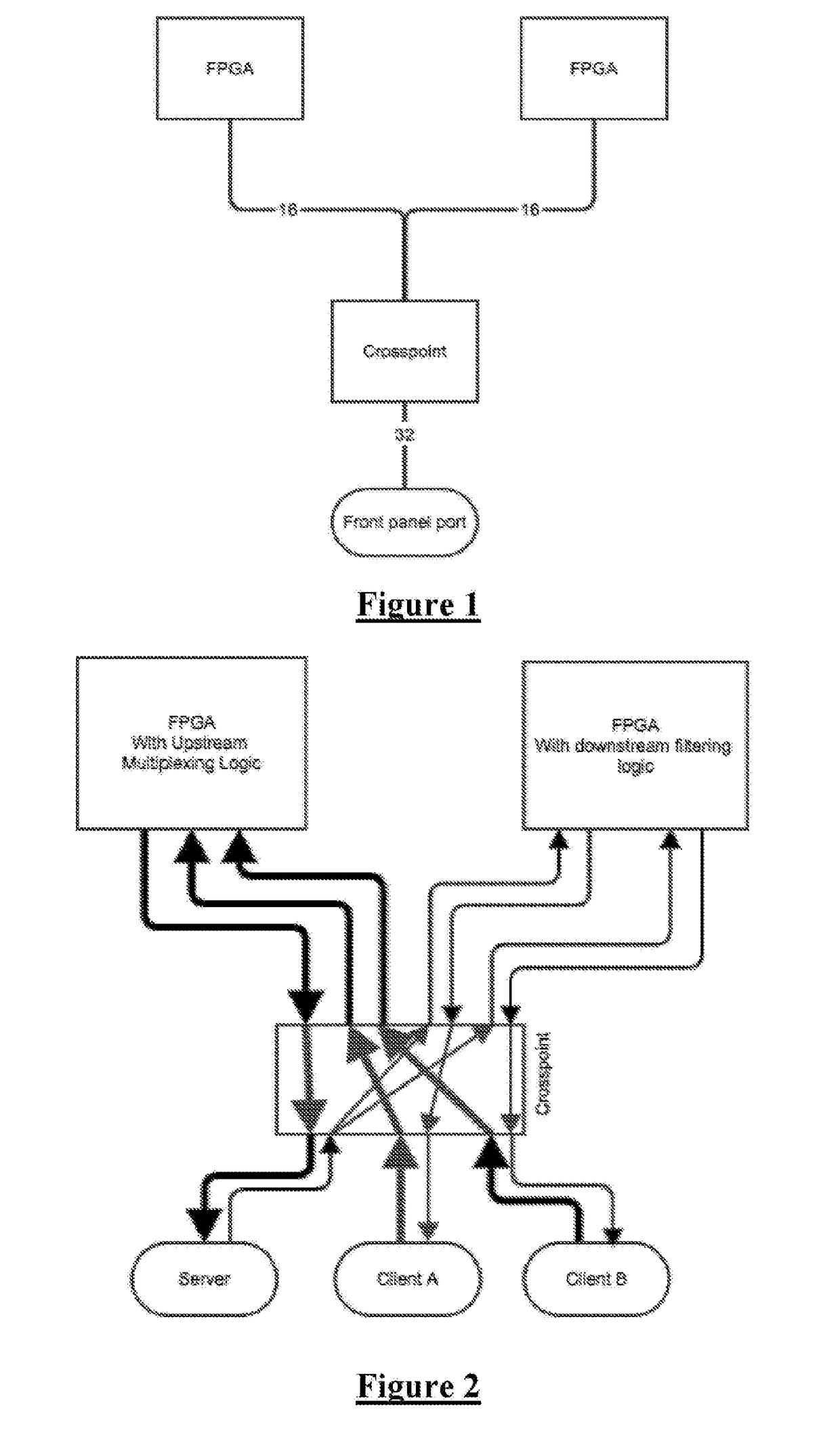
[0108]FIG. 1 is a system schematic of the hardware used to implement one embodiment of the present invention. It consists of some front panel ports which can be connected to other devices, some FPGAs which have transceivers which can talk to the front panel ports, and a crosspoint switch which can remap, as well as multicast data from one port to multiple ports. It is noted that not all of the cross point outputs will necessarily be connected to the logic functions of the FPGAs as some ports will be needed to provide data output to external devices.

[0109]For the upstream component of the device of FIG. 1, the device provides an FPGA which takes a number of input streams and multiplexes them into one. This single multiplexed stream is then returned through the crosspoint switch. Since there is very little other logic in the device, there is little congestion, which means the FPGA can be driven at high clock rates, with short pipelines or groupings of logic components in the FPGA. Tha...


PUM


Abstract

A method of data switching. Data is received at least one input port of a crosspoint switch. The crosspoint switch configurably casts the data to at least one output port of the crosspoint switch. The or each output port of the crosspoint switch is connected to a respective input of a logic function device such as a FPGA. The logic function device applies a logic function to data received from the or each output port of the crosspoint switch, such as address filtering or multiplexing, and outputs processed data to one or more respective logic function device output interfaces. Also, a method of switching involving circuit switching received data to an output while also copying the data to a higher layer function.

Description

CROSS-REFERENCE TO RELATED APPLICATIONS[0001]This application claims the benefit of Australian Provisional Patent Application Nos. 2014903158 and 2014904247, filed 13 Aug. 2014 and 23 Oct. 2014 respectively, each of which is incorporated herein by reference.TECHNICAL FIELD[0002]The present invention relates to network data switching, and in particular to an efficient low latency data switch using a combination of one or more crosspoint switches with one or more logic function devices such as FPGAs or ASICs, to implement desired networking functionality.BACKGROUND OF THE INVENTION[0003]It is often desirable to take data packets from one source and to send the data packets to one or more of a number of possible destinations. This is the case in the downstream direction from a stock exchange, for example, where it is desirable for a number of machines such as stock traders' computers to potentially receive packets from the exchange.[0004]In some applications it is appropriate to broadc...

Claims


Application Information

Patent Timeline
Patent Type & Authority Applications(United States)
IPC IPC(8): H04L12/931H04L12/743H04L12/933H04L47/56H04L49/111
CPCH04L49/201H04L45/7457H04L49/101G06F13/00H04L12/413H04L49/15G06F15/17H04L49/30H04L45/74591
Inventor SNOWDON, DAVIDMCDAID, SCOTTTHOMAS, CHARLESPOWLES, LINDSAY
Owner ARISTA NETWORKS
Why Eureka
Try Eureka