
Stand for electronic device

a technology for electronic devices and stands, which is applied in the direction of machine supports, casings/cabinets/drawers, casings/cabinets/drawers details, etc., can solve the problems of not preventing the drop of electronic devices, prone to being accidentally dropped, hit or scratched, and the difficulty of holding a large electronic mobile device in one hand for many users, so as to achieve the effect of not adding unnecessary bulk

Active Publication Date: 2017-05-11
SPIGEN KOREA
View PDF10 Cites 23 Cited by
  • Summary
  • Abstract
  • Description
  • Claims
  • Application Information

AI Technical Summary

Benefits of technology

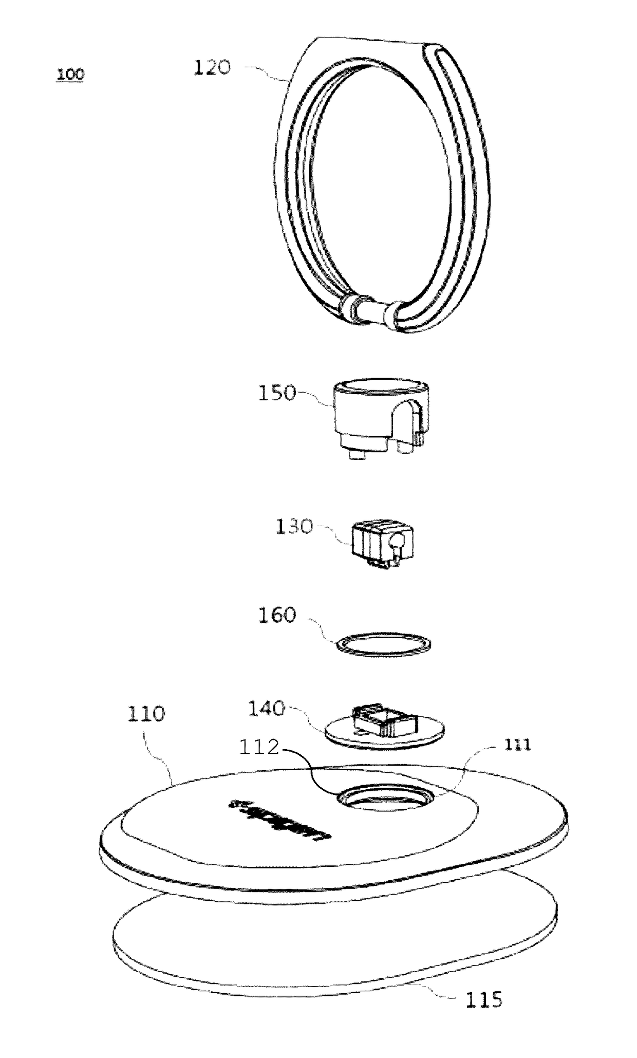
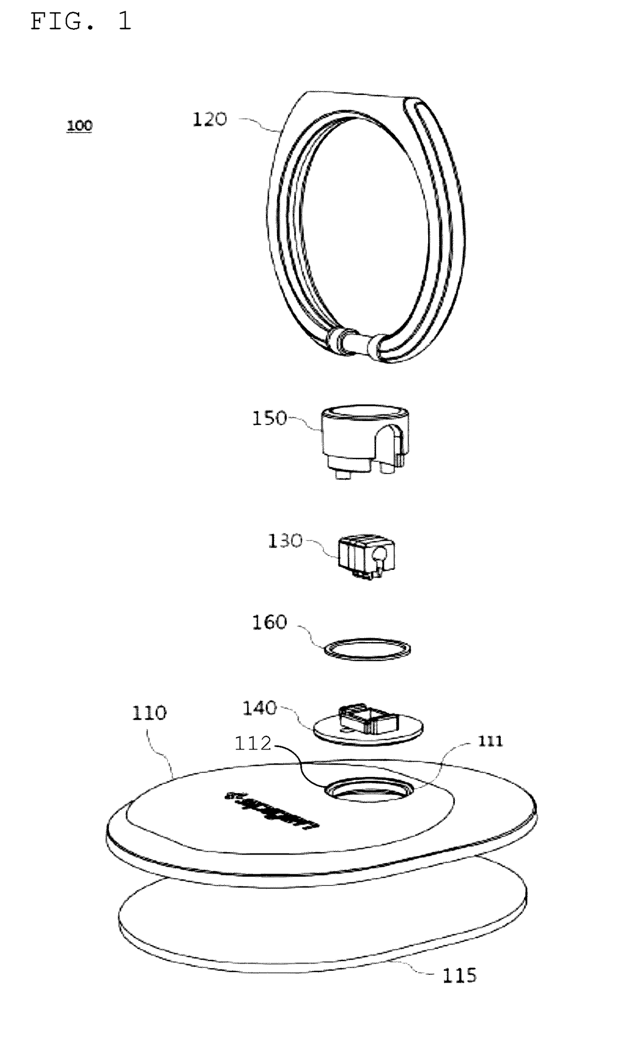
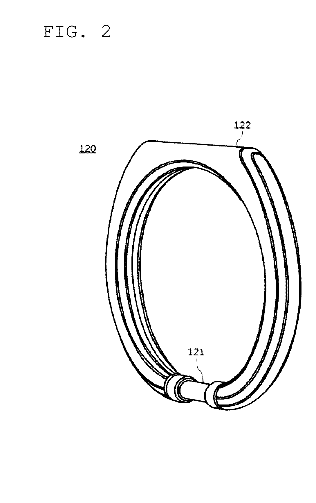
The present invention is a stand for an electronic device that provides portability without adding unnecessary bulk. The stand allows the user to easily hold the electronic device or stand it at various angles on a flat surface. The stand has a ring structure that allows the user to conveniently and hold the electronic device by inserting their finger. It has a complicated structure that can be conveniently and effectively manufactured. The stand also has a holder that can be attached to various surfaces, making it convenient for users to mount the electronic device on different surfaces. The stand is slim and compact.

Problems solved by technology

These electronic devices are intended to be carried or moved about and as such, they are prone to being accidentally dropped, hit, or scratched.
However, while such protective films for display and protective cases may help to reduce damage when electronic devices are dropped, they will not prevent the electronic devices from being dropped.
Accordingly, these larger electronic mobile devices have become more difficult to hold in one hand for many users and have necessitated a way to more securely and conveniently grasp such devices.
However, the handle and coil adds undesirable bulk and weight to the smartphone and, thus, the user may have an uncomfortable experience using the smartphone and difficulty for conveniently and holding it.
Thus, such a handle cannot satisfy a user's need for conveniently holding an electronic device and the need for easily standing the electronic device at various angles of tilt on a surface to view video content while maintaining the portability of such an electronic device.

Method used


Image

  • Stand for electronic device
  • Stand for electronic device
  • Stand for electronic device

Examples


Embodiment Construction

[0045]Reference will now be made in detail to the preferred embodiments of the present invention, examples of which are illustrated in the accompanying drawings, which form a part of this disclosure. It is to be understood that this invention is not limited to the specific devices, methods, conditions or parameters described and / or shown herein, and that the terminology used herein is for the purpose of describing particular embodiments by way of example only and is not intended to be limiting of the claimed invention.

[0046]Also, as used in the specification including the appended claims, the singular forms “a”, “an”, and “the” include the plural, and reference to a particular numerical value includes at least that particular value, unless the context clearly dictates otherwise. Ranges may be expressed herein as from “about” or “approximately” one particular value and / or to “about” or “approximately” another particular value. When such a range is expressed, another embodiment includ...


PUM


Abstract

A stand for an electronic device includes a base, a ring, a hinge, a cover and a hinge receiving wall and an adhesive provided on a surface of the base so that the base can be attached to the electronic device. The ring further includes a cylindrical engaging portion on a portion of the ring. The hinge includes a protrusion and an engaging groove which is formed by a cutout space on a side of the hinge. The hinge is received a shape corresponding to the engaging portion of the ring in the engaging groove. The cover for covering the hinge in the cover is received a shape corresponding to the hinge to snugly fit the hinge therein. The hinge receiving wall receives the protrusion of the hinge.

Description

CROSS-REFERENCE TO RELATED APPLICATIONS[0001]This application claims priority of Korean Application No. 20-2015-0007224, filed Nov. 06, 2015 with the Korean Intellectual Property Office, the disclosure of which is incorporated herein by reference.FIELD OF THE INVENTION[0002]The present invention relates to a stand for an electronic mobile device, and more particularly, to a stand having a base, a ring and an adhesive pad. The stand is securely attached to the electronic device, and thus the user can securely and conveniently use the electronic device whether the user is holding it or if it is self-standing or mounted on a surface.BACKGROUND OF THE INVENTION[0003]Electronic devices, such as mobile phones, cell phones, smart phones, tablet computers or the like, have become popular and widely used for communication, entertainment purposes and other purposes. These electronic devices are intended to be carried or moved about and as such, they are prone to being accidentally dropped, hi...

Claims


Application Information

Patent Timeline
IPC IPC(8): H05K5/02H05K5/03F16B11/00F16M13/02E05D11/00E05D3/02
CPCH05K5/0234E05D11/0054E05D3/022H05K5/03F16M13/02H05K5/0226F16B11/006H04M1/04F16M11/10F16M11/2014F16M13/04E05Y2999/00H05K7/00A45F5/00F16M13/00
Inventor KIM, DAE-YOUNG
Owner SPIGEN KOREA
Learn More