Brush

Inactive Publication Date: 2017-05-25
BYRD RUBIA
View PDF9 Cites 2 Cited by
  • Summary
  • Abstract
  • Description
  • Claims
  • Application Information

AI Technical Summary

Benefits of technology

The present invention is a brushing device with a unique angle adjustment mechanism and attachment mechanism. The brushing component of the device is attached to the base at an angle, which results in a more effective cleaning, scrubbing, sweeping, and painting technique. The device also has a retractable member and a handle at the aft end, making it easy to use. Overall, the present invention provides a more efficient and effective brushing experience.

Problems solved by technology

The difficulty of reaching corners and baseboards when cleaning and painting has long been recognized.
In the case of mopping a floor, it is difficult to reach the corners of a floor with a traditional mop.
However, such a brush is typically rectangular and includes bristles which are vertical, thereby forming a 90 degree angle when in use.
Vertical bristles do not allow the user to easily reach the corner due to the presence of the handle and part of the brush holding the bristles.
The same issue is present when cleaning or painting walls.
This is time consuming and typically requires a latter in order to reach the entire wall.
In addition, baseboards and ceiling moldings are difficult to clean using traditional cleaning supplies.
A typical mop often fails to deliver enough force to clean baseboards.
This usually results in the user cleaning the baseboards using a towel.
In the case of ceiling moldings cleaning using a rag is typically not an option.
Unfortunately, a duster spreads dust throughout the area below the ceiling moldings.
Similar to the issues presented when cleaning a floor, the corners of a shower present even more of an issue.
A typical prior art mop or foam sponge / mop simply does not clean out the corners.

Method used


Image

  • Brush
  • Brush
  • Brush

Examples


Embodiment Construction

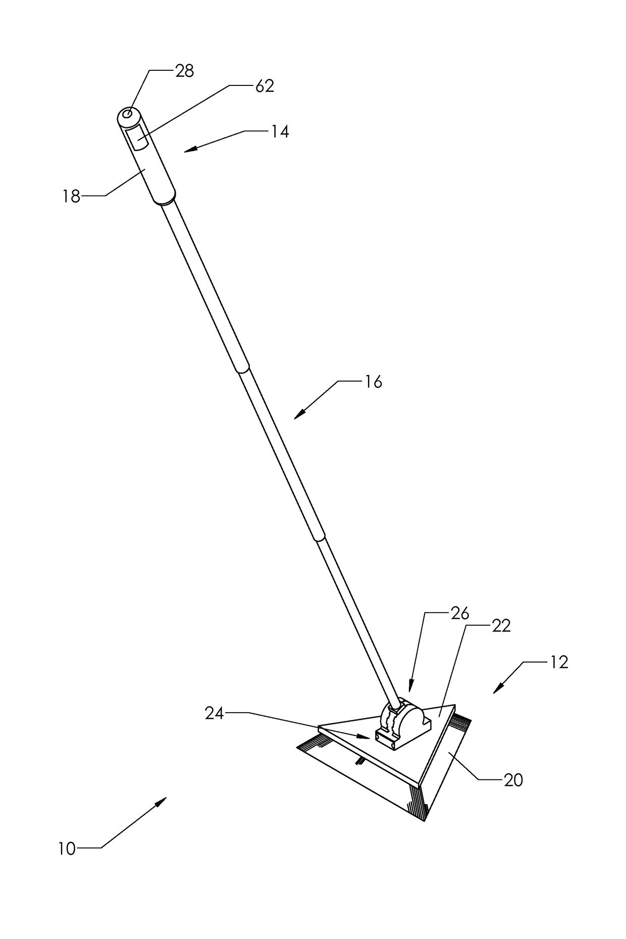
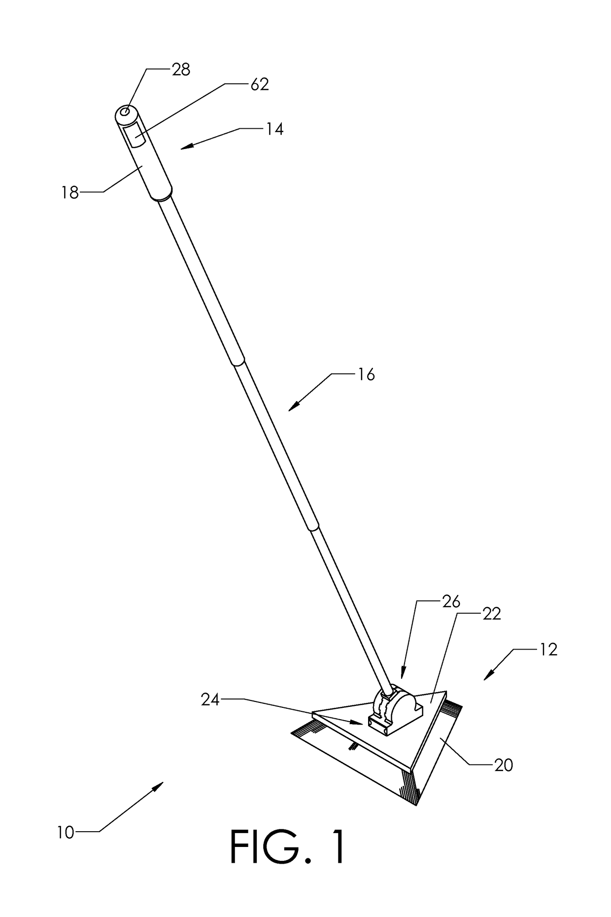
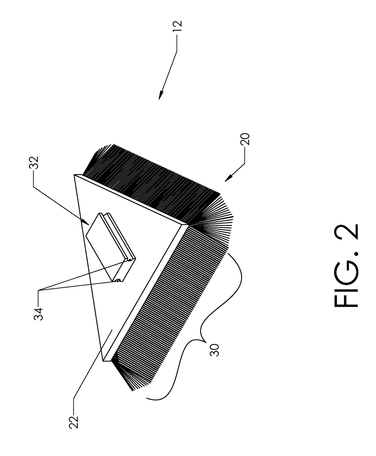
[0054]The present invention provides a brushing device for use in various hard-to-reach places around a household or workplace. FIG. 1 shows a preferred embodiment of the present invention. Brushing device 10 includes forward end 12, aft end 14, and member 16. As illustrated, member 16 connects forward end 12 to aft end 14. Aft end 14 includes handle 18. Forward end 12 includes brushing component 20 which is attached to base 22. As shown, brushing component 20 is attached to the bottom side of base 22. The top side of base 22 includes an attachment mechanism 24. In some embodiments of the present invention, base 22 is integral to member 16. However, member 16 is preferably removably attached to base 22 as illustrated in FIG. 1. Brushing device 10 includes an angle adjustment mechanism 26, which allows the user to adjust the angle of member 16 with respect to the horizon.

[0055]Member 16 preferably comprises multiple sections of hollow tubing. These sections progressively decrease in ...


PUM


Abstract

A brushing device which includes a forward end, an aft end, and a member there between. Preferably, the aft end includes a handle. In some embodiments, the member is retractable. In a preferred embodiment of the present invention, the forward end includes a base, a brushing component, an angle adjustment mechanism, and an attachment mechanism. Preferably, the brushing component of the present invention is attached to the base such that the brushing component extends outward laterally from the base at an angle with the horizontal plane which is less than 90 degrees. In some embodiments of the present invention, the base of the brushing device is triangular. However, some embodiments of brushing device include a round or rectangular base. In addition, the brushing component can take many forms. One such form is bristles. In some instances, the brushing component is a sponge.

Description

BACKGROUND OF THE INVENTION[0001]1. Field of the Invention[0002]This invention relates to the field of brush devices. More specifically, the invention comprises a brushing device which is capable of accessing places which are difficult to reach.[0003]2. Description of the Related Art[0004]The difficulty of reaching corners and baseboards when cleaning and painting has long been recognized. This is true while mopping a floor, cleaning or painting walls, cleaning a shower, and washing base boards or ceiling molding. In the case of mopping a floor, it is difficult to reach the corners of a floor with a traditional mop. Even with a mop that is capable of reaching the corners of a floor, such as a rectangular foam mop, the mop just forces the dirt into the corners. This leads one wishing to clean the corners of a floor to use a brush with bristles. However, such a brush is typically rectangular and includes bristles which are vertical, thereby forming a 90 degree angle when in use. Verti...

Claims


Application Information

Patent Timeline
IPC IPC(8): B08B1/00B08B9/04A46B9/00B25G1/06B25G1/04
CPCB08B1/002B25G1/06B08B9/04A46B9/005B25G1/04A47L13/20B08B1/00B08B9/0436E03C1/30B25G3/02B25G3/38A46B2200/3033A46B2200/3073B08B1/12
Inventor BYRD, RUBIA
Owner BYRD RUBIA
Why Eureka
Try Eureka