Volatile substance evaporator with substance end-of-life detector

a technology of end-of-life detector and volatile substance, which is applied in the direction of liquid/fluent solid measurement, insect catchers and killers, animal husbandry, etc., can solve the problems of lack of geometric accuracy, low light transmission efficiency through the wick, and difficulty in detecting the level of liquid remaining in the container at first sigh

Active Publication Date: 2011-12-01
ZOBELE ESPANA
View PDF7 Cites 3 Cited by
  • Summary
  • Abstract
  • Description
  • Claims
  • Application Information

AI Technical Summary

Benefits of technology

The present invention generally relates to volatile substance evaporators having a container with a wick, and has the object of providing an effective technique for detecting end-of-life of the volatile substance housed within the container.

Problems solved by technology

These devices are generally plugged into out-of-sight household power outlets, due to which the level of liquid remaining in the container is not easily seen at first sight.
Detection systems for detecting liquid at the bottom of the container, for example, by means of light transmission, have the following drawbacks:High degree of dispersion due to the lack of geometric accuracy of the bottles generally used.Influence of external conditions (sunlight, reflections, .
These systems have the following drawbacks:Need to adjust the position of the light emitter / sensor based on the refractive index of the fragrance.Influence of external conditions (sunlight, reflections, .
However, when there is liquid the light is refracted or reflected and does not reach the sensor.
The drawbacks of these systems are the following:Light transmission through the wick is not very efficient and requires a high-sensitivity sensor.In order for light transmission to be sufficiently efficient, specific wick characteristics are required (pore size, pore percentage, .
. . ).Possible interference by ambient light.The light emitter and sensor must be aligned facing each other, which entails technical difficulties for reducing position tolerances.
The drawbacks of this system are the following:It requires an adequate positioning of the emitter so that the light enters the container at certain angles.The container must be made of glass.

Method used


Image

  • Volatile substance evaporator with substance end-of-life detector
  • Volatile substance evaporator with substance end-of-life detector
  • Volatile substance evaporator with substance end-of-life detector

Examples


Embodiment Construction

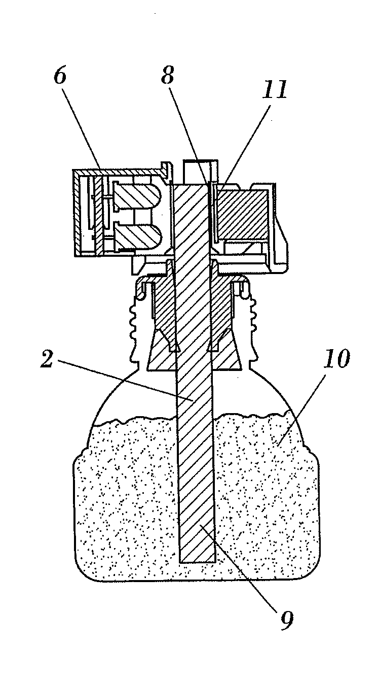
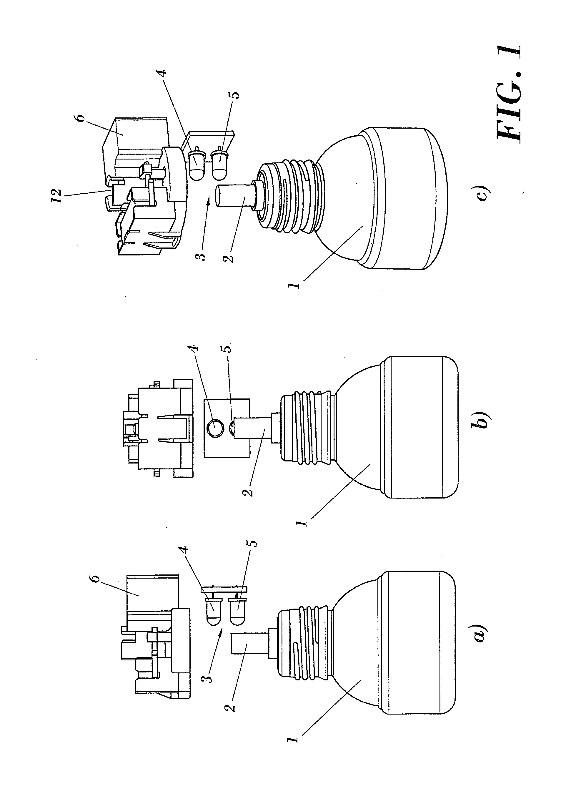
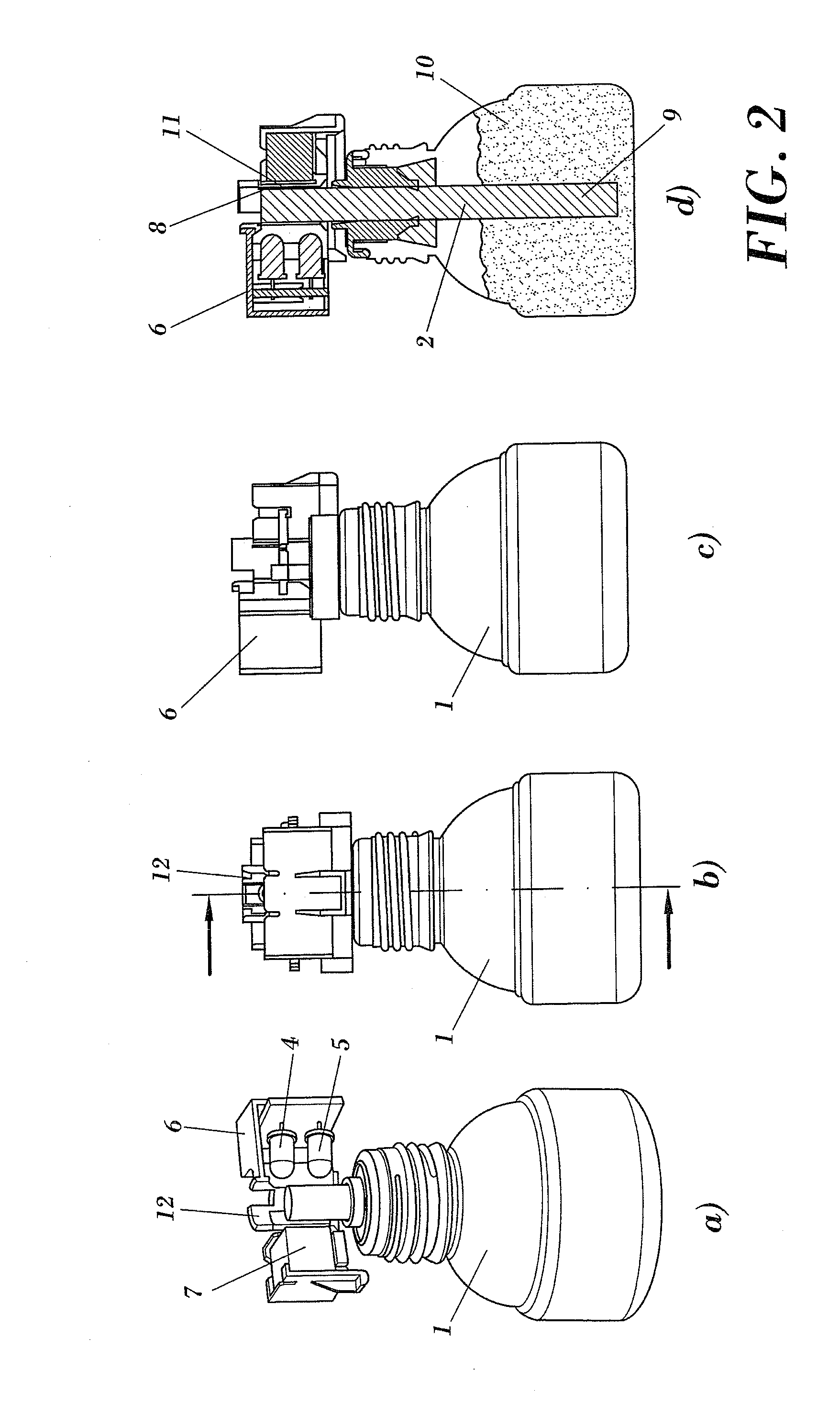
The present invention relates to a volatile substance evaporator device having means to detect end-of-life of the substance to be evaporated. The evaporator is configured for coupling to, and maintaining in a stable position, a container with a volatile substance having a porous wick partially immersed in the substance container and with an upper end emerging from the container.

By wick we understand any type of adequate capillary medium for correctly transporting liquid from the container to the evaporation zone. Ceramic or fibre wicks having cylindrical geometry are the most common embodiments. But the wick may also have a flat geometry. Even capillary channels machined into the wall of a non-porous solid support are susceptible to being used as wicks in the present invention.

The evaporator comprises an infrared light and emitter and receptor, where the emitter is disposed so as to emit a beam of light on the end or upper part of the wick, and the receptor is disposed so as to capt...


PUM

PropertyMeasurementUnit
wavelengthaaaaaaaaaa
wavelength rangeaaaaaaaaaa

Abstract

The present invention generally relates to volatile substance evaporators having a container with wick, and has the object of providing a technique for effectively detecting end-of-life of the volatile substance housed within the container. The volatile substance evaporator is configured for coupling to, and maintaining in a stable position, a container of volatile substance having a wick with a lower end housed within said container and an upper end emerging from the container. The evaporator comprises an infrared light emitter disposed so as to emit a beam of light on said upper end of the wick, in such a manner that a receptor is disposed so as to capture said beam of light reflected by the upper end of the wick.

Description

OBJECT OF THE INVENTIONThe present invention generally relates to volatile substance evaporators having a container with a wick, and has the object of providing an effective technique for detecting end-of-life of the volatile substance housed within the container.BACKGROUND OF THE INVENTIONIn volatile substance diffuser devices with wick, there is a need to allow the user to easily detect end-of-life of the volatile substance and therefore perceive the need to replace the container of the substance with a new one. These devices are generally plugged into out-of-sight household power outlets, due to which the level of liquid remaining in the container is not easily seen at first sight.There are several solutions for converting end-of-life into an electric indicator that can then imply some type of alert to the user. These systems are based on the measurement of a change in physical properties, such as electrical conductivity, dielectric capacity, weight, temperature or light interact...

Claims


Application Information

Patent Timeline
Patent Type & Authority Applications(United States)
IPC IPC(8): A61L9/04
CPCA01M1/2077G01F23/292A61L9/127A61L9/037A01M1/20A61L9/12
Inventor RIERA GINER, MONTSERRATMAYOR SANS, FERNANDOMORHAIN, CEDRICGARCIA FABREGA, RUBEN
Owner ZOBELE ESPANA
Why Eureka
Try Eureka