

Sweeping machine with multi-component moldboard
- Summary
- Abstract
- Description
- Claims
- Application Information
AI Technical Summary
Benefits of technology
Problems solved by technology
Method used
Image

Examples
Embodiment Construction
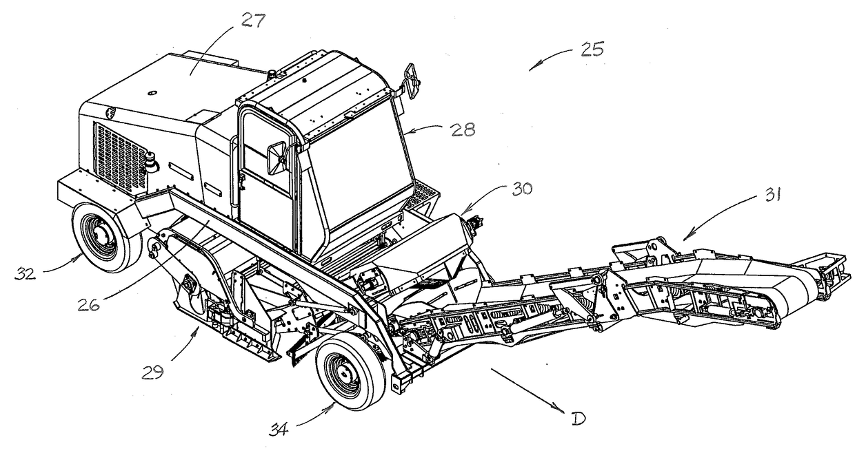
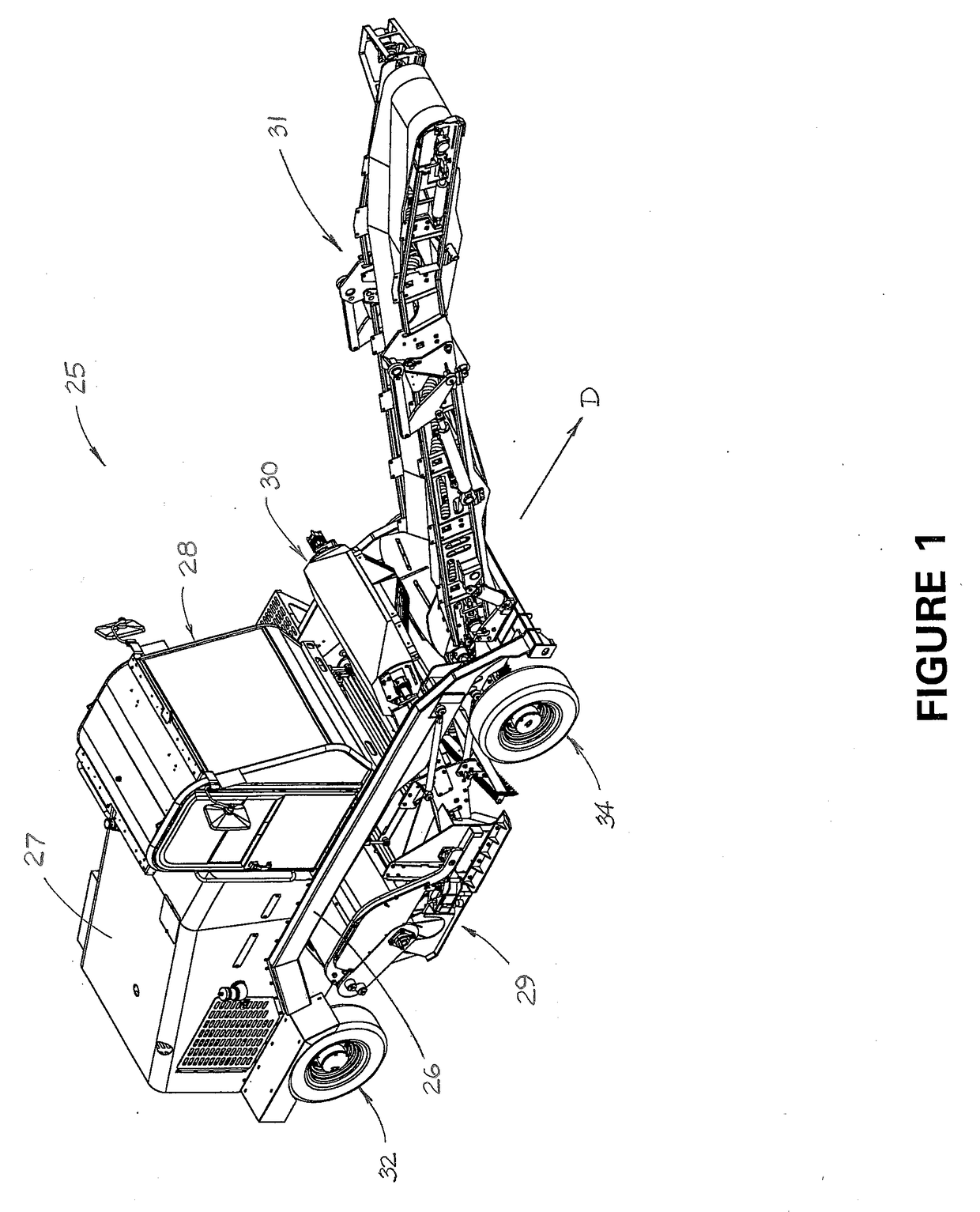
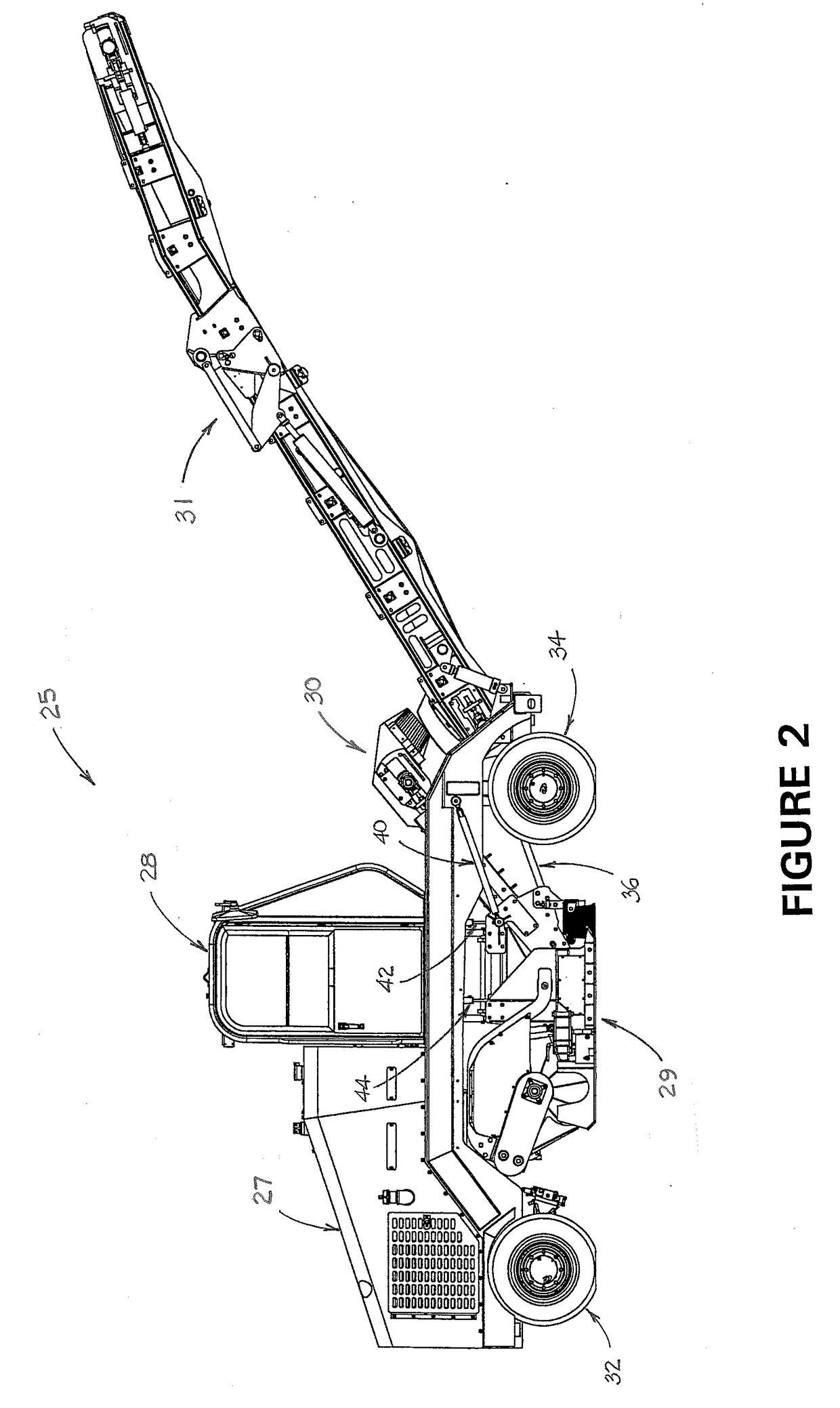
[0023]The invention comprises a vehicular sweeping machine having a frame and a broom enclosure for enclosing a broom comprising a generally cylindrical tube with attached bristles that is adapted to rotate about a generally horizontal axis. The broom enclosure includes a left end gate, a right end gate and a moldboard assembly. The moldboard assembly comprises an outer moldboard and an inner moldboard which are arranged to form a labyrinth seal at the rear of the broom enclosure. A broom conveyor has a lower end that is disposed within the broom enclosure.
[0024]A particularly preferred embodiment of the invention comprises a broom assembly that is adapted for removal and replacement of brooms from the side of the machine. Still another preferred embodiment of the invention comprises a broom assembly that is mounted on the frame in such a manner that it may be moved vertically with respect to the frame in order to improve the seal of the broom assembly with respect to the roadway. Y...
PUM
 Abstract
Description
Claims
Application Information