Downhole Tool having Slips Set by Stacked Rings

a technology of stacked rings and tools, applied in the field of downhole tools, can solve the problems of limited contact area between slips and cones, failure to achieve successful attempts, and collapse of cones of element systems, etc., and achieve the effect of decreasing spacing and decreasing spacing

Inactive Publication Date: 2017-05-25
WEATHERFORD TECH HLDG LLC
View PDF2 Cites 3 Cited by
  • Summary
  • Abstract
  • Description
  • Claims
  • Application Information

AI Technical Summary

Benefits of technology

[0027]A drive sleeve disposed on the mandrel move the first shoulder. A lock disposed between the drive sleeve and the mandrel can permit movement of the drive sleeve toward the second shoulder, but prevents reverse movement of the drive sleeve. The first shoulder can have a catch at least temporarily holding an end of the slip. For its part, the second shoulder can be a sleeve fixed on the mandrel.
[0031]The spacings in between the stacked rings can expand the second of the stacked rings outward at one of the opposing shoulders before the other opposing shoulder. Also, the stacked rings can have contact angles disposed adjacent one another, and the contact angles can expand the second of the stacked rings outward at one of the opposing shoulders before the other opposing shoulder.

Problems solved by technology

In one continuing problem associated with conventional element systems of these types of downhole tools, the cones of the element systems can collapse.
Attempts to design a convention downhole tool, such as a packer, capable of handling 10,000-psi or greater cone collapse pressure have been made, and testing has proven these attempts to be unsuccessful.
One issue that prevents increased cone collapse pressures one conventional downhole tools is the limitations in the contact area between the slips and the cones when set into the tubular or casing.

Method used


Image

  • Downhole Tool having Slips Set by Stacked Rings
  • Downhole Tool having Slips Set by Stacked Rings
  • Downhole Tool having Slips Set by Stacked Rings

Examples


Embodiment Construction

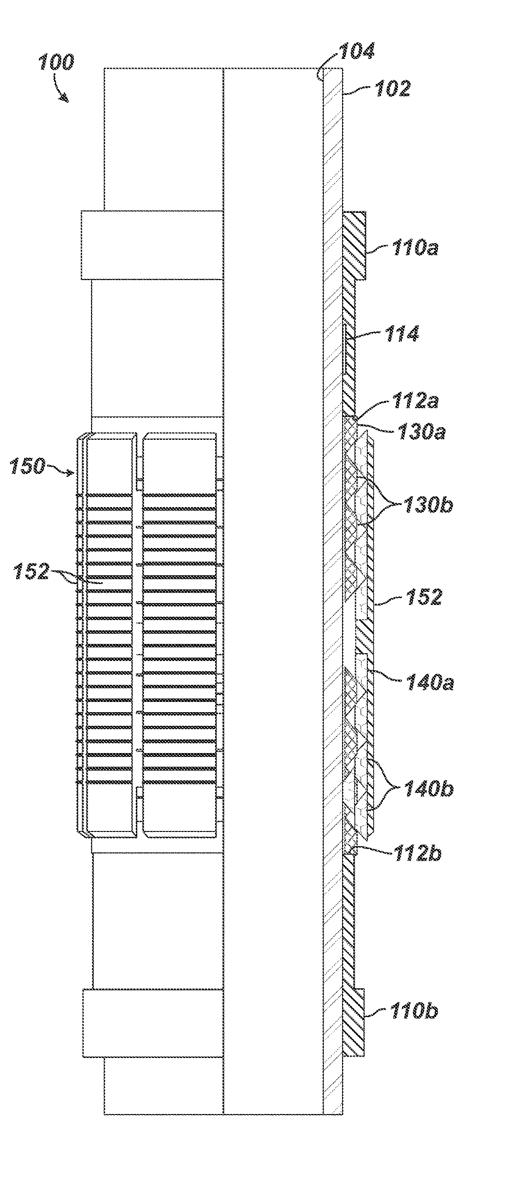
[0059]FIGS. 3A-3B illustrate a downhole tool 100 according to the present disclosure in partial cross-section in a run-in condition. The downhole tool 100 can be configured as a bridge plug, a frac plug, a packer, or any other desired downhole packer tool. In a particular example, the downhole tool 100 can be a permanent sump packer used as a base for a cased-hole gravel pack completion.

[0060]The downhole tool 100 has a mandrel 102, first and second opposing shoulders 112a-b, a plurality of stacked rings 130a-b and 140a-b, and a slip 150. The first and second opposing shoulders 112a-b are disposed on the mandrel 110, and at least one of the opposing shoulders (e.g., the first shoulder 112a) is movable toward the second opposing shoulder 112b. These opposing shoulders 112a-b can be part of sleeves 110a-b disposed on the mandrel 102. In this context, the first sleeve 110a can be a drive sleeve movable along the mandrel 102 toward the second, fixed sleeve 110b. (FIG. 6 shows an isolate...


PUM


Abstract

An apparatus installs downhole in a surrounding tubular. A first shoulder on a mandrel of the apparatus is movable toward a second shoulder. A plurality of stacked rings are disposed about the mandrel and are spaced between the first and second shoulders. A first of the stacked rings decreases in spacing in response to the movement of the first shoulder toward the second shoulder, and a second of the stacked rings expands outward from the mandrel in response to the decrease in spacing. A slip disposed on the stacked rings is movable away from the mandrel toward the surrounding tubular in response to the outward expansion. The apparatus can be a plug, a bridge plug, a fracture plug, a packer, a permanent packer, a retrievable packer, a sump packer, and a sealbore packer. Additionally, the apparatus can include a completion assembly with packer and screen supported on the mandrel.

Description

CROSS-REFERENCE TO RELATED APPLICATIONS[0001]This application claims the benefit of U.S. Provisional Appl. 62 / 081,753, filed 19 Nov. 2014, which is incorporated herein by reference.TECHNICAL FIELD[0002]The present disclosure relates to the field of downhole tools, and in particular to downhole tools, such as bridge plugs, frac-plugs, and packers.BACKGROUND ART[0003]An oil or gas well includes a wellbore extending into a well to some depth below the surface. Typically, the wellbore is lined with tubulars or casing to strengthen the walls of the borehole. To strengthen the walls of the borehole further, the annular area formed between the casing and the borehole is typically filled with cement to set the casing permanently in the wellbore. Perforating the casing then allows production fluid to enter the wellbore and flow to the surface of the well.[0004]Downhole tools with sealing elements, such as plugs or packers, are placed within the wellbore to isolate the production fluid or to ...

Claims


Application Information

Patent Timeline
Patent Type & Authority Applications(United States)
IPC IPC(8): E21B33/129E21B23/01
CPCE21B33/1291E21B33/128E21B23/01E21B33/129E21B33/1293E21B33/134
Inventor CASTRO, CANDIDORITCHEY, BRIAN J.
Owner WEATHERFORD TECH HLDG LLC
Why Eureka
Try Eureka