Device for Switching a First and Second Switching Element, and Transmission Comprising Such a Device

a technology of shifting elements and switching elements, which is applied in the direction of mechanical actuation clutches, interengaging clutches, and can solve the problems of increasing the complexity and the error rate of transmission, and the poor accessibility of shifting elements in transmissions with one or even a multiple number of planetary gear sets coupled to each other, so as to achieve reliable and simple actuation

Inactive Publication Date: 2017-05-25
ZF FRIEDRICHSHAFEN AG
View PDF38 Cites 1 Cited by
  • Summary
  • Abstract
  • Description
  • Claims
  • Application Information

AI Technical Summary

Benefits of technology

[0006]Therefore, exemplary aspects of the invention provide a device for shifting two shifting elements, whic...

Problems solved by technology

On the other hand, transmissions with one or even a multiple number of planetary gear sets coupled to each other feature s...

Method used


Image

  • Device for Switching a First and Second Switching Element, and Transmission Comprising Such a Device
  • Device for Switching a First and Second Switching Element, and Transmission Comprising Such a Device
  • Device for Switching a First and Second Switching Element, and Transmission Comprising Such a Device

Examples


first embodiment

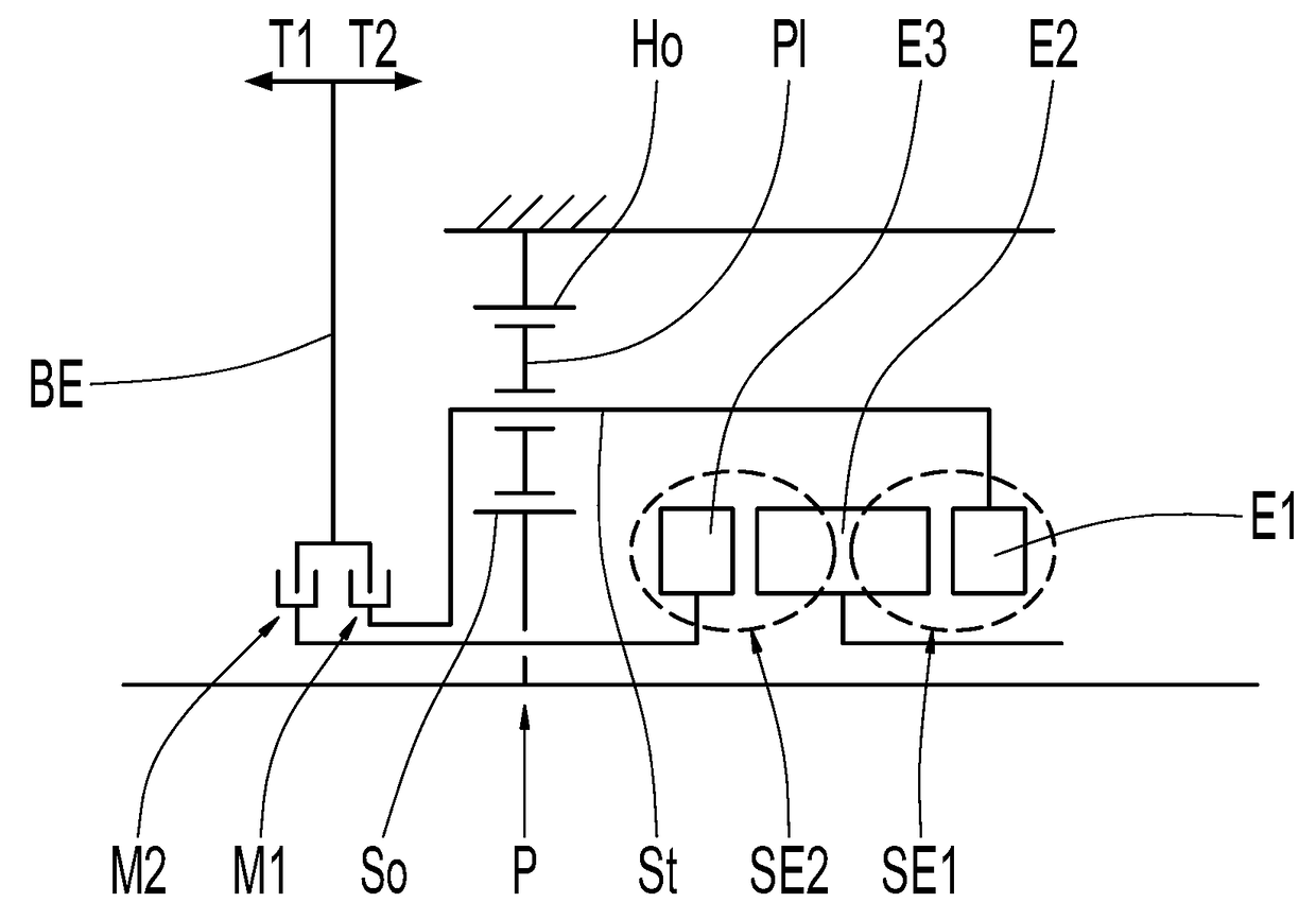
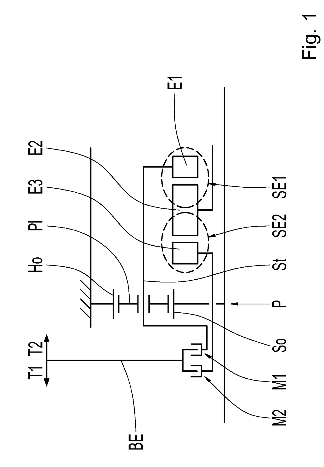
[0040]FIG. 1 schematically shows the shifting device. A planetary gear set P comprises a sun gear So, a carrier St, at least one planetary gear PI and a ring gear Ho. The ring gear Ho is constantly fixed in a torque-proof manner. The sun gear So is constantly connected to a first shaft. An actuating element BE, which is longitudinally displaceable in two directions by an actuator (not shown), is arranged on a first side of the planetary gear set P. A second shaft is located on a second side opposite to the first side of the planetary gear set P. The second shaft is to assume, optionally, the rotational speed of the sun gear So, the rotational speed of the carrier St or a free rotational speed.

[0041]On the second side of the planetary gear set P, a first element E1, a second element E2 and a third element E3 are arranged, which together form a first shifting element SE1 and a second shifting element SE2. The second shaft is fixed in an axial manner by a mounting (not shown) and is co...

third embodiment

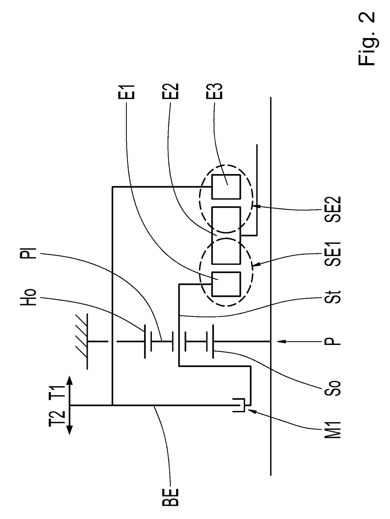
[0048]In the third embodiment, the ring gear Ho or the shaft connected to it, as the case may be, forms the second element E2 of the device. Through the first element E1, a torque-proof, positive-locking connection can be established at a section of the shaft that is connected to the first segment Ho-1. Through the third element E3, a torque-proof, positive-locking connection can be represented at a section of the shaft that is connected to the second segment Ho-2. For this purpose, two spatially separated synchronization toothings are formed at the second element E2. The ring gear Ho and the shaft or shaft sections, as the case may be, connected to it are fixed in the axial direction by a suitable mounting (not shown).

[0049]The first element E1 is connected in a torque-proof manner to the first shaft, and is displaceable in an axial manner at this shaft. The third element E3 is connected in a torque-proof manner to a torque-proof component, such that the third element E3 cannot ass...


PUM


Abstract

A shifting device includes a first shifting element operable to establish a torque-proof, positive-locking connection between a first element and a second element. A second shifting element is operable to establish a torque-proof, positive-locking connection between the second element and a third element. The first element is coupled to the third element such that displacement of the first element by a common actuating element in one of a first and a second displacement direction provides rectified displacement of the third element. The third element is coupled to the first element such that displacement of the third element by the common actuating element in one of the first and second displacement directions provides rectified displacement of the first element. The second element is fixed in position in both the first and second displacement directions. A related transmission is also provided.

Description

FIELD OF THE INVENTION[0001]The invention relates generally to a device for shifting a first shifting element and a second shifting element, whereas the first shifting element can establish a torque-proof, positive-locking connection between a first element and a second element, and whereas the second shifting element can establish a torque-proof, positive-locking connection between the second element and a third element, whereas the actuation of the first shifting element and the second shifting element takes place through the longitudinal displacement of a common actuating element, whereas the first shifting element is closed and the second shifting element is open in a first shifting state, whereas the first shifting element is open and the second shifting element is closed in a second shifting state, along with a transmission for a motor vehicle with such a device.BACKGROUND[0002]Devices for shifting a first shifting element and a second shifting element are used, in particular,...

Claims


Application Information

Patent Timeline
IPC IPC(8): F16H3/66F16H63/20F16D11/14
CPCF16H3/66F16D11/14F16H2200/2064F16H2200/2007F16H2200/2094F16H63/20F16H3/44F16H59/02F16H63/30F16H63/32F16H2063/322B60K6/365B60K6/387B60K6/547F16H3/725F16H63/3069F16H2200/201F16H2200/2023F16H2200/2046
Inventor ZIEMER, PETER
Owner ZF FRIEDRICHSHAFEN AG
Why Eureka
Try Eureka