Universally applicable centrifuge plate for casting housing ends of hollow fiber filter modules

Active Publication Date: 2017-06-01
B BRAUN AVITUM
View PDF8 Cites 3 Cited by
  • Summary
  • Abstract
  • Description
  • Claims
  • Application Information

AI Technical Summary

Benefits of technology

[0008]It is a particular advantage of the invention that the elements and units of known centrifuge plates, such as for instance supporting pins, star-shaped distributors and axial housing clamping means can be broadly used within the scope of the invention. In this way, it is possible to have recourse to established products, while at the same time the benefits provided by the invention can be utilized. According to aspects of the invention, the rotatable bearing elements are arranged or formed instead of mounts comprising exchangeable housing supports. They can be implemented in particular in the form of rotary plates. Due to the rotatable arrangement of the bearing elements, the latter can be positioned relative to each other and relative to the centrifuge plate in a simple way. In doing so, the accessibility to the bearing elements is not inhibited. This offers the possibility to receive different housing geometries in a universal centrifuge plate and to cast them there, wherein the process of aligning the bearing elements allows to simply adapt the centrifuge plate to different housings.
[0009]The alignment of the bearing elements is carried out preferably prior to the charging by an automated handling from above. Alternatively, the alignment may be carried out manually or from below. For adapting them to different housings, the bearing elements are simply swiveled or rotated around their rotational axis and in this way can be positioned or aligned in different receiving positions, wherein each receiving position is designed, adapted and intended for receiving a particular type of housing. The information needed for the respectively required alignment of the bearing elements can be provided and controlled by a machine control system. The positioning of the bearing elements can be detected visually and/or by machine.
[0010]Advantageous embodiments of the invention are claimed in the sub-claims and explained in more detail below.
[0

Problems solved by technology

It is a particular disadvantage that the use of such exchange parts does not allow an automated manufacture, in particular not an automated casting of hollow fiber filter module housings.
However, this centrifuge plate is quite high and needs a high technical effort for an automat

Method used


Image

  • Universally applicable centrifuge plate for casting housing ends of hollow fiber filter modules
  • Universally applicable centrifuge plate for casting housing ends of hollow fiber filter modules

Examples


Embodiment Construction

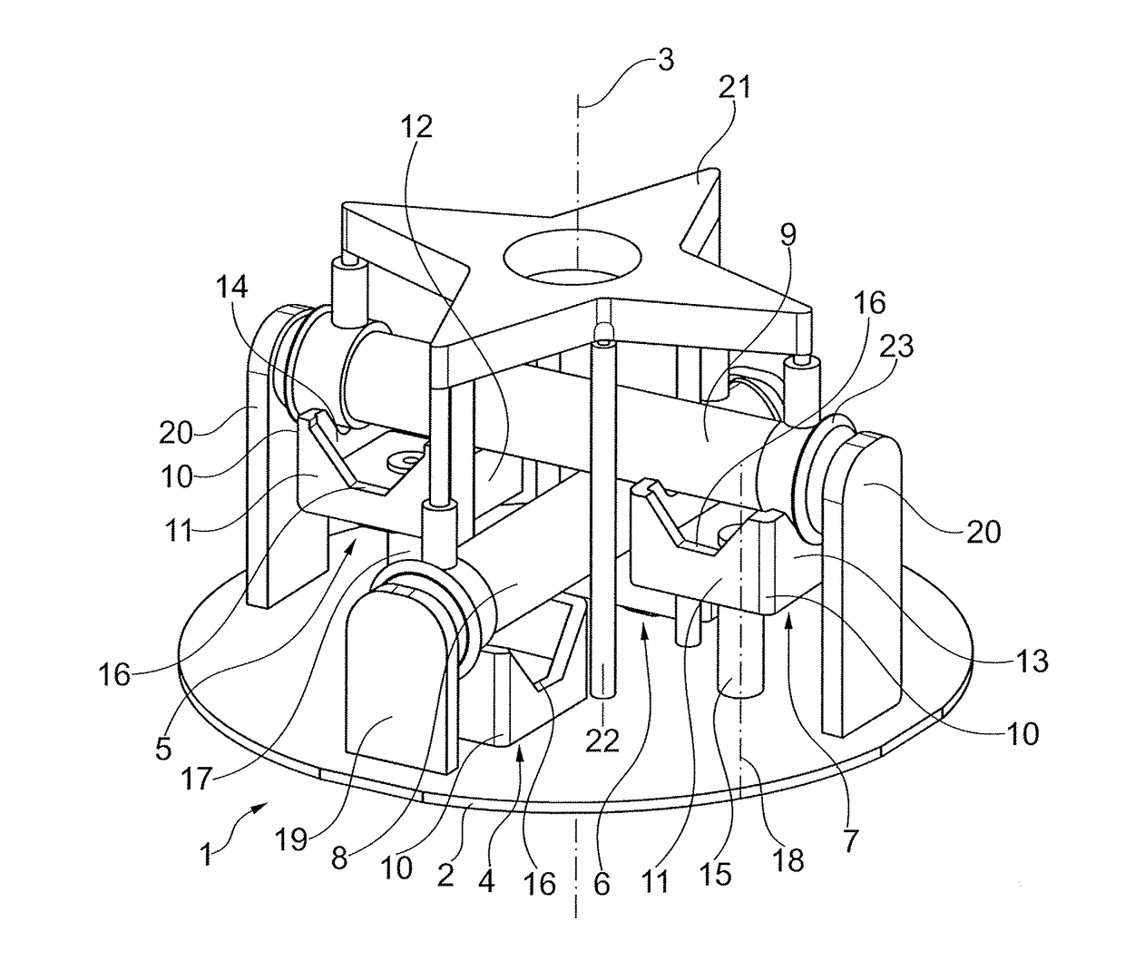
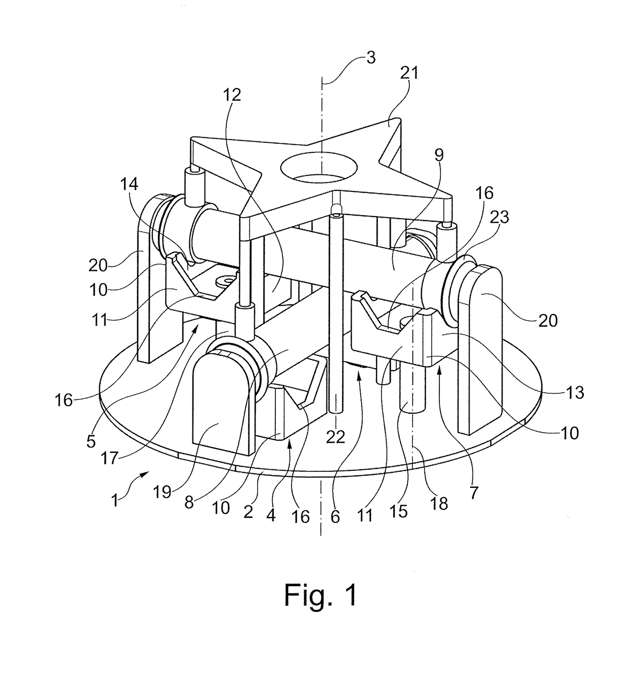
[0026]In the illustrated embodiment, four bearing elements 4, 5, 6, 7 are arranged on the base 2. The bearing elements 4 and 6 as well as 5 and 7 form bearing element pairs each serving to support an essentially cylindrical housing 8 and 9, respectively, of a hollow fiber filter module to be cast. The bearing elements 4 and 6 are situated diametrically opposite each other with respect to the centrifuge axis 3. The bearing elements 5 and 7 are also located diametrically opposite each other with respect to the centrifuge axis 3. The pair of the bearing elements 4 and 6 is turned by an angle of 90° in the plane of the base 2 with regard to the pair of the bearing elements 5 and 7.

[0027]Each of the bearing elements 4, 5, 6, 7 comprises a bearing head 10. Said head has a square cross-section in a plane parallel to the base 2 and transverse to the centrifuge axis 3. As a result, the bearing head 10 comprises four side walls 11, 12, 13, 14 each defining a receiving structure 16 in the form...


PUM


Abstract

A centrifuge plate is disclosed which is intended for casting housing ends of hollow fiber filter modules and can be rotated around a centrifuge axis. The centrifuge plate includes at least two bearing elements arranged diametrically with respect to the centrifuge axis and provided for supporting a housing of a hollow fiber filter module to be cast, wherein each bearing element is rotatably supported on the centrifuge plate around a bearing axle which is parallel to the centrifuge axis.

Description

CROSS REFERENCE TO RELATED APPLICATIONS[0001]This application claims priority to German Application DE 10 2015 120 761.3 filed Nov. 30, 2015, the contents of such application being incorporated by reference herein.FIELD OF THE INVENTION[0002]The invention relates to a universally applicable centrifuge plate for casting housing ends of hollow fiber filter modules.BACKGROUND OF THE INVENTION[0003]In the production of hollow fiber filter modules according to the prior art, production methods are known in which the housing ends of a more or less elongated and hollow cylindrical housing of a hollow fiber filter module comprising hollow fibers received in the longitudinal direction therein is cast with a casting compound. It is known to cast both ends of a housing at the same time using a centrifuge. Due to the centripetal force acting therein, the casting compound accumulates at both ends of the housing. To this end, a housing of a hollow fiber filter module comprising a fiber bundle ins...

Claims


Application Information

Patent Timeline
IPC IPC(8): B29C39/02B29C39/26
CPCB29C39/02B29C39/26B29L2022/00B01D2313/21B01D63/021B29C41/042B01D63/022B29C39/08B29C39/10B29C39/22B29C41/20B29C41/34B29C70/845B29L2031/14B29L2031/753
Inventor KASTNER, FALK
Owner B BRAUN AVITUM
Why Eureka
Try Eureka