Ionizing Radiation Detector

a detector and ionizing radiation technology, applied in the field of electromagnetic detection systems, can solve problems such as difficulty in construction and implementation

Active Publication Date: 2022-02-03
THE JOHN HOPKINS UNIV SCHOOL OF MEDICINE
View PDF3 Cites 0 Cited by
  • Summary
  • Abstract
  • Description
  • Claims
  • Application Information

AI Technical Summary

Benefits of technology

[0007]According to some example embodiments, an ionizing radiation detector is provided. The ionizing radiation detector may comprise a first common semiconductor substrate and a first plurality of single-photon avalanche diode (SPAD) microcell structures disposed at a top face of the first common semiconductor substrate. In this regard, each SPAD microcell structure of the first plurality of SPAD microcell structures may comprise a first semiconductor junction that is reverse-biased beyond a first breakdown threshold for the first semiconductor junction. The ionizing radiation detector may also comprise a common anode connection and a common cathode connection to each of the SPAD microcell structures of the first plurality of SPAD microcell structures. These connections may be configured to operate as an output for the first plurality of SPAD microcell structures. The ionizing radiation detector may also comprise control circuitry connected to the first plurality of SPAD microcell structures. The control circuitry may be configured to control biasing of the first plurality of SPAD microcell structures, and measure electrical characteristics of a signal provided on the output. According to some example embodiments, the charge drift within the first common semiconductor substrate need not be inhibited from exciting more than one of the SPAD microcell structures of the first plurality of SPAD microcell structures by isolation barriers.
[0008]Another example embodiment is a SPAD array for an ionizing radiation detector. The SPAD array may comprise a first common semiconductor substrate, and a first plurality of SPAD microcell structures disposed at a top face of the first common semiconductor substrate. Each SPAD microcell structure of the first plurality of SPAD microcell structures may comprise a first semiconductor junction that is reverse-biased beyond a first breakdown threshold for the first semiconductor junction. The SPAD array may further comprise a common anode connection and a common cathode connection to each of the SPAD microcell structure of the first plurality of SPAD microcell structures and configured to operate as an output for the SPAD array. Further, charge drift within the first common semiconductor substrate need not be inhibited from exciting more than one of the SPAD microcell structures of the first plurality of SPAD microcell structures by isolation barriers.
[0009]According to some example embodiments, an example method associated with operation of a ionizing radiation detector is also provided. In this regard, the example method may comprise controlling biasing of a first plurality of SPAD microcell structures disposed at a top face of a first common semiconductor substrate of an ionizing radiation detector. Each SPAD microcell structure of the first plurality of SPAD microcell structures may comprise a first semiconductor junction that is reverse-biased beyond a first breakdown threshold for the first semiconductor junction. The example method may also include receiving ionizing radiation at the ionizing radiation detector. Additionally, the example method may comprise permitting charge drift within a first common semiconductor substrate in response to receipt of ionizing radiation to excite one or more of the SPAD microcell structures of a first plurality of SPAD microcell structures. In this regard, the charge drift need not be inhibited from exciting more than one of SPAD microcell structures of a first plurality of SPAD microcell structures by isolation barriers. Further, the example method may comprise measuring electrical characteristics of a signal provided on a output of the first plurality of SPAD microcell structures. The output of the first plurality of SPAD microcell structures may comprise a common anode connection and a common cathode connection to each of the SPAD microcell structures of the first plurality of SPAD microcell structures.

Problems solved by technology

Both of these approaches of ionizing radiation detection have certain complexities and drawbacks that, in some instances, make them difficult to construct and implement.

Method used


Image

  • Ionizing Radiation Detector
  • Ionizing Radiation Detector
  • Ionizing Radiation Detector

Examples


Embodiment Construction

[0023]Some non-limiting, example embodiments now will be described more fully hereinafter with reference to the accompanying drawings, in which some, but not all example embodiments are shown. Indeed, the examples described and pictured herein should not be construed as being limiting as to the scope, applicability or configuration of the present disclosure. Rather, these example embodiments are provided so that this disclosure will satisfy applicable legal requirements. Like reference numerals refer to like elements throughout.

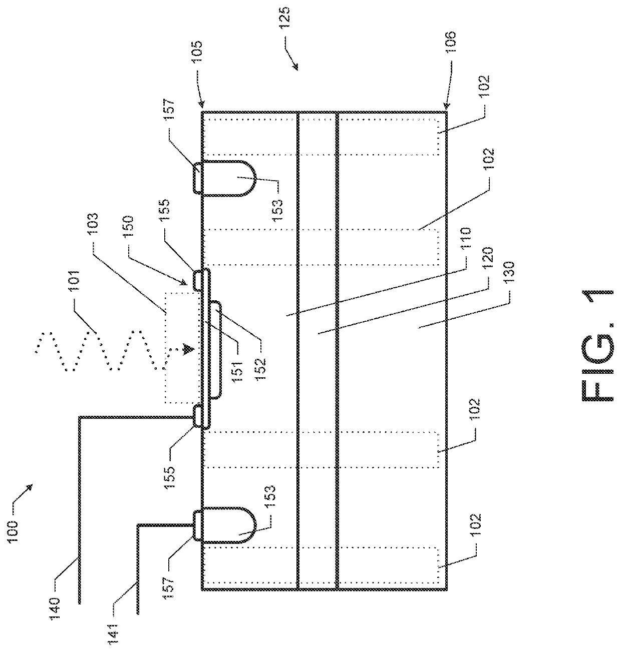
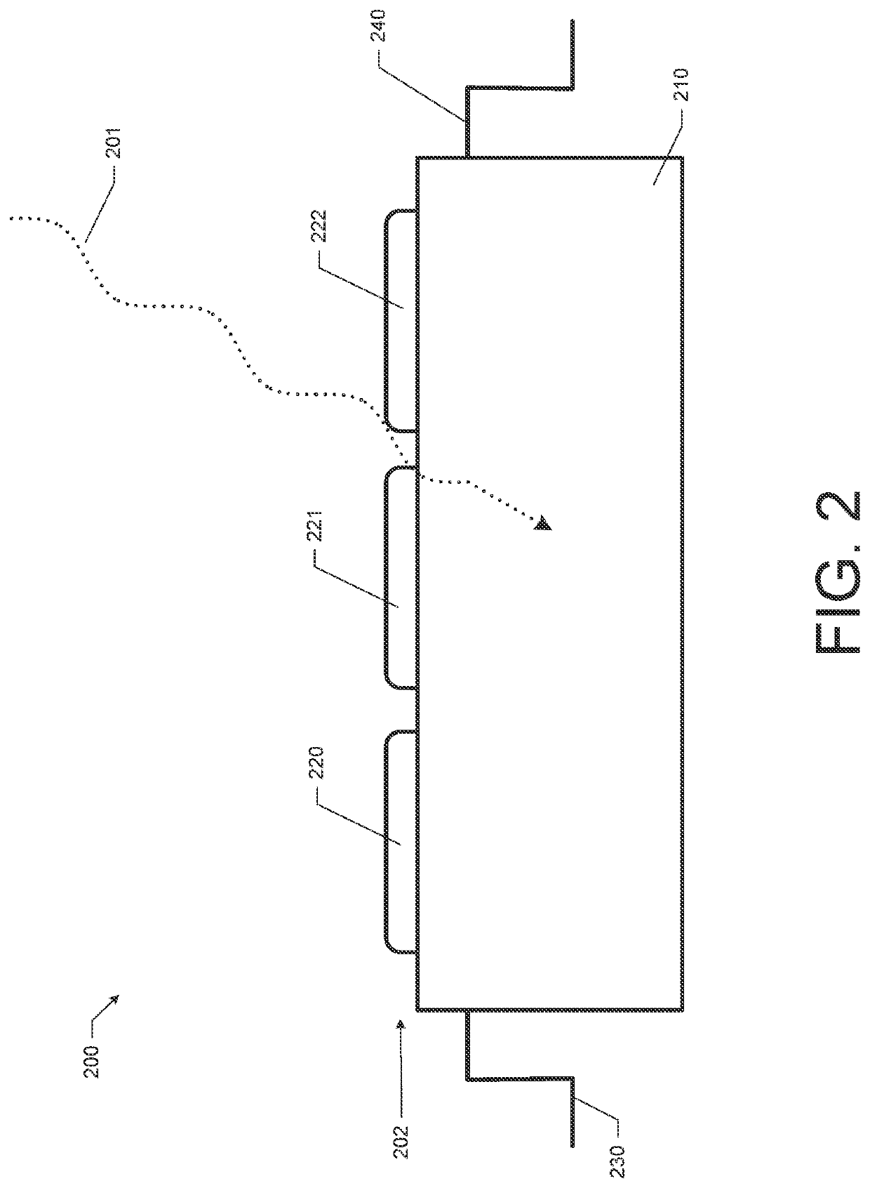
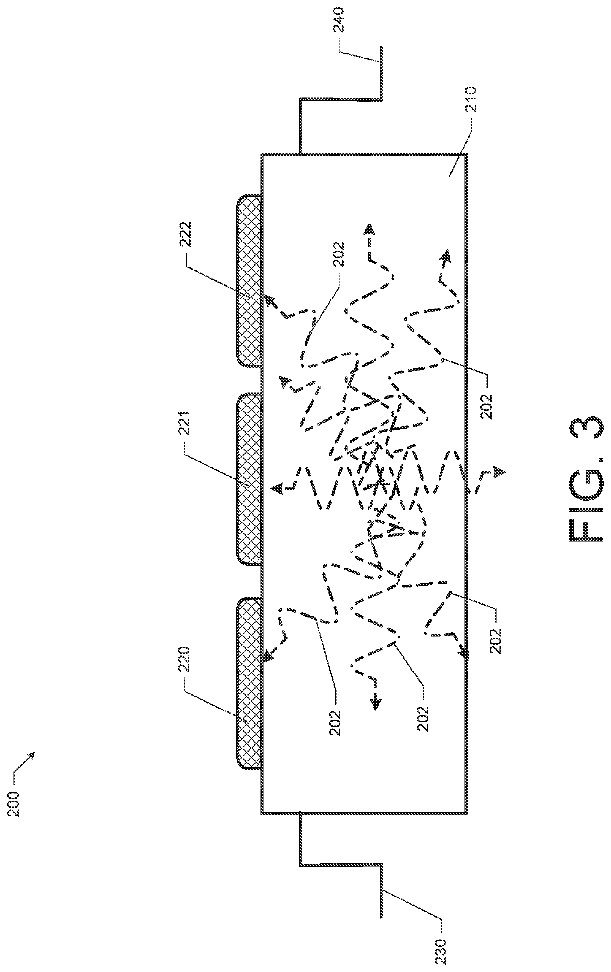
[0024]According to some example embodiments, an ionizing radiation detector comprising a SPAD array and associated methods and systems are provided that leverage uninhibited charge drift and visible light that is released during a photon-electron collision or ionization event to obtain information regarding ionizing radiation. In many conventional systems, the charge drift between components and the output of visible light is considered a nuisance that is fil...


PUM


Abstract

An ionizing radiation detector includes a first common semiconductor substrate and a first plurality of single-photon avalanche diode (SPAD) microcell structures disposed at a top face of the first common semiconductor substrate. Each SPAD microcell structure includes a first semiconductor junction that is reverse-biased beyond a first breakdown threshold. The ionizing radiation detector may also include common anode and cathode connections to each of the SPAD microcell structures that operate as an output. The ionizing radiation detector may also include control circuitry connected to the SPAD microcell structures. The control circuitry may be configured to control biasing of the SPAD microcell structures and measure electrical characteristics of a signal provided on the output. Charge drift within the first common semiconductor substrate need not be inhibited from exciting more than one of the SPAD microcell structures of the first plurality of SPAD microcell structures by isolation barriers.

Description

CROSS-REFERENCE TO RELATED APPLICATIONS[0001]This application claims priority to and the benefit of prior-filed, co-pending U.S. Provisional Application No. 63 / 060,180 filed on Aug. 3, 2020 and U.S. Provisional Application No. 63 / 158,935 filed on Mar. 10, 2021, the entire contents of both of which are incorporated by reference herein.TECHNICAL FIELD[0002]Exemplary embodiments of the present disclosure generally relate to electromagnetic detection systems. Further, many of the example embodiments provided herein more specifically relate to ionizing radiation detection technologies that leverage charge drift and visible light release generated by interactions with ionizing radiation.BACKGROUND[0003]The ability to detect ionizing radiation has proven to be a valuable in a number of different applications. For example, the detection of ionizing radiation or the presence of high energy particles has applications in nuclear physics research, and in industrial and medical procedures to nam...

Claims


Application Information

Patent Timeline
Patent Type & Authority Applications(United States)
IPC IPC(8): G01T1/24G01T1/20G01T1/208
CPCG01T1/248G01T1/208G01T1/2018H01L27/14603H01L27/14601
Inventor LAVELLE, CHRISTOPHER M.
Owner THE JOHN HOPKINS UNIV SCHOOL OF MEDICINE
Why Eureka
Try Eureka