Force sensor-based motion or orientation determination in a device

a technology of force sensor and motion or orientation determination, which is applied in the direction of electric digital data processing, instruments, computing, etc., can solve the problems and achieve the effect of saving cost and/or space in the devi

Active Publication Date: 2017-06-01
APPLE INC
View PDF6 Cites 21 Cited by
  • Summary
  • Abstract
  • Description
  • Claims
  • Application Information

AI Technical Summary

Benefits of technology

[0005]Some electronic devices can include touch screens that may include force sensing capabilities—that is, they may be able to detect an amount of force with which an object is touching the touch screens. These forces can constitute force inputs to the electronic devices for performing various functions, for example. In some examples, the force sensing capabilities in the touch screens may provide motion- or orientation-dependent outputs. It can be beneficial to use those outputs to determine the motion and / or orientation of the touch screens, or the electronic devices in which they are integrated. In this way, discrete accelerometer and / or gyroscope circuitry may not be required to be included in the electronic devices, potentially saving cost and / or space in the device. In some examples, the above-mentioned force sensing capability in an electronic device can be provided by utilizing a flex layer that can be relatively free-moving, and thus can deflect to various degrees when the electronic device in which the touch screen is integrated is experiencing motion or changes in orientation. These deflections in the flex layer can be sensed to determine one or more characteristics of the motion and / or orientation of the electronic device. Various examples of the above are provided in this disclosure.

Problems solved by technology

In this way, discrete accelerometer and / or gyroscope circuitry may not be required to be included in the electronic devices, potentially saving cost and / or space in the device.

Method used


Image

  • Force sensor-based motion or orientation determination in a device
  • Force sensor-based motion or orientation determination in a device
  • Force sensor-based motion or orientation determination in a device

Examples


Embodiment Construction

[0032]In the following description of examples, reference is made to the accompanying drawings which form a part hereof, and in which it is shown by way of illustration specific examples that can be practiced. It is to be understood that other examples can be used and structural changes can be made without departing from the scope of the disclosed examples.

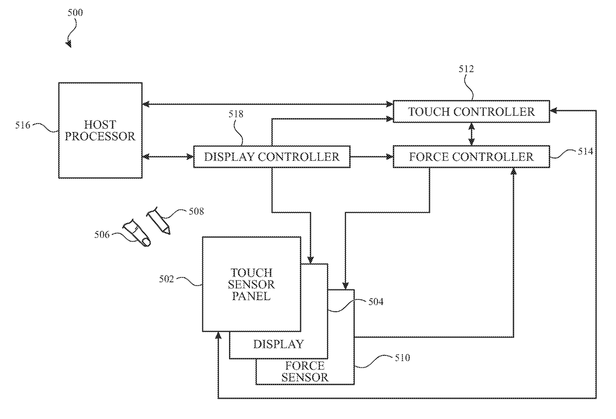
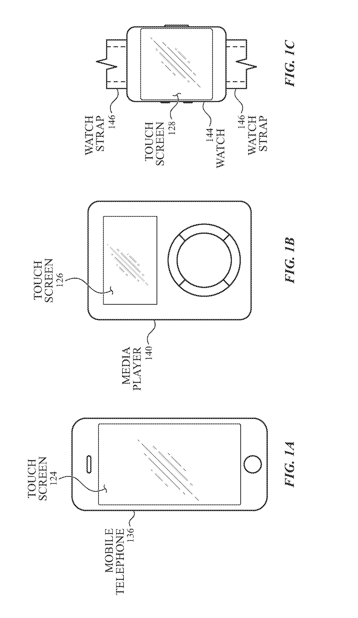
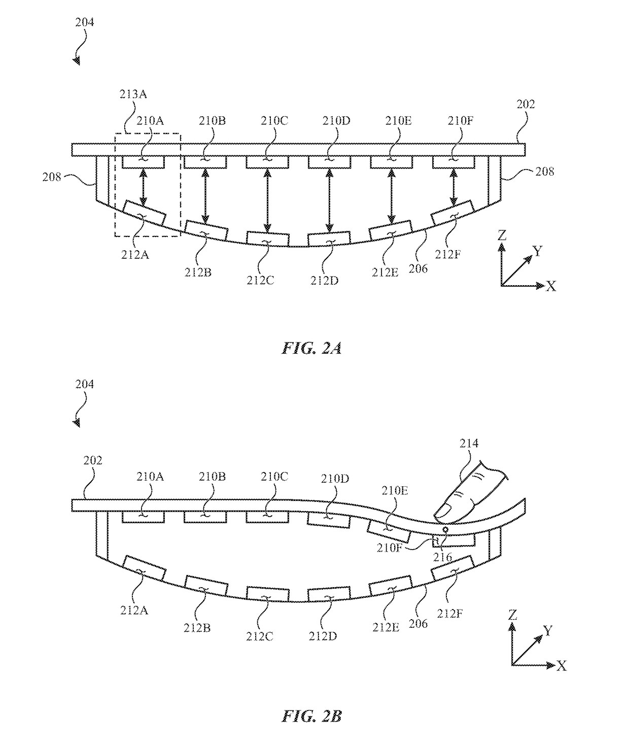
[0033]Some electronic devices can include touch screens that may include force sensing capabilities—that is, they may be able to detect an amount of force with which an object is touching the touch screens. These forces can constitute force inputs to the electronic devices for performing various functions, for example. In some examples, the force sensing capabilities in the touch screens may provide motion- or orientation-dependent outputs. It can be beneficial to use those outputs to determine the motion and / or orientation of the touch screens, or the electronic devices in which they are integrated. In this way, discrete accelero...


PUM


Abstract

An electronic device is disclosed. The electronic device comprises a touch sensor panel configured to detect an object touching the touch sensor panel and a plurality of force sensors coupled to the touch sensor panel and configured to detect an amount of force with which the object touches the touch sensor panel. A processor is coupled to the plurality of force sensors, the processor configured to: measure a first value from a first force sensor of the plurality of force sensors; measure a second value from a second force sensor of the plurality of force sensors, different from the first force sensor; and determine a motion characteristic of the electronic device based on the first value and the second value.

Description

CROSS-REFERENCE TO RELATED APPLICATIONS[0001]This application claims benefit of U.S. Provisional Patent Application No. 62 / 261,832, filed Dec. 1, 2015 and U.S. Provisional Patent Application No. 62 / 261,835, filed Dec. 1, 2015, which are hereby incorporated by reference in their entirety.FIELD OF THE DISCLOSURE[0002]This relates generally to determining the motion and / or orientation of an electronic device, and more particularly, to doing so using one or more force sensors integrated in the electronic device.BACKGROUND OF THE DISCLOSURE[0003]Many types of input devices are presently available for performing operations in a computing system, such as buttons or keys, mice, trackballs, joysticks, touch electrode panels, touch screens and the like. Touch screens, in particular, are becoming increasingly popular because of their ease and versatility of operation as well as their declining price. Touch screens can include a touch electrode panel, which can be a clear panel with a touch-sen...

Claims


Application Information

Patent Timeline
Patent Type & Authority Applications(United States)
IPC IPC(8): G06F3/041G06F3/044
CPCG06F3/044G06F3/0414G06F1/1626G06F1/1643G06F1/1694G06F3/04144G06F3/04166G06F3/0418G06F3/0443G06F3/0445G06F3/0446G06F3/0447G06F2200/1637G06F2203/04106G06F3/002
Inventor CHAWDA, VINAYGOWREESUNKER, VIKRHAMBIJAMOV, ALEX
Owner APPLE INC
Why Eureka
Try Eureka