Non-pneumatic tire

a non-pneumatic, tire technology, applied in the direction of wheels, high resiliency wheels, vehicle components, etc., can solve the problems of requiring compressed fluid, pneumatic tires, and conventional pneumatic tires being rendered useless

Active Publication Date: 2017-06-08
THE GOODYEAR TIRE & RUBBER CO
View PDF5 Cites 13 Cited by
  • Summary
  • Abstract
  • Description
  • Claims
  • Application Information

AI Technical Summary

Problems solved by technology

The primary drawback to a pneumatic tire is that it requires compressed fluid.
A conventional pneumatic tire is rendered useless after a complete loss of inflation pressure.
Structurally supported tires such as sold tires or other elastomeric structures to date have not provided the levels of performance required from a conventional pneumatic tire.

Method used


Image

  • Non-pneumatic tire
  • Non-pneumatic tire
  • Non-pneumatic tire

Examples


Embodiment Construction

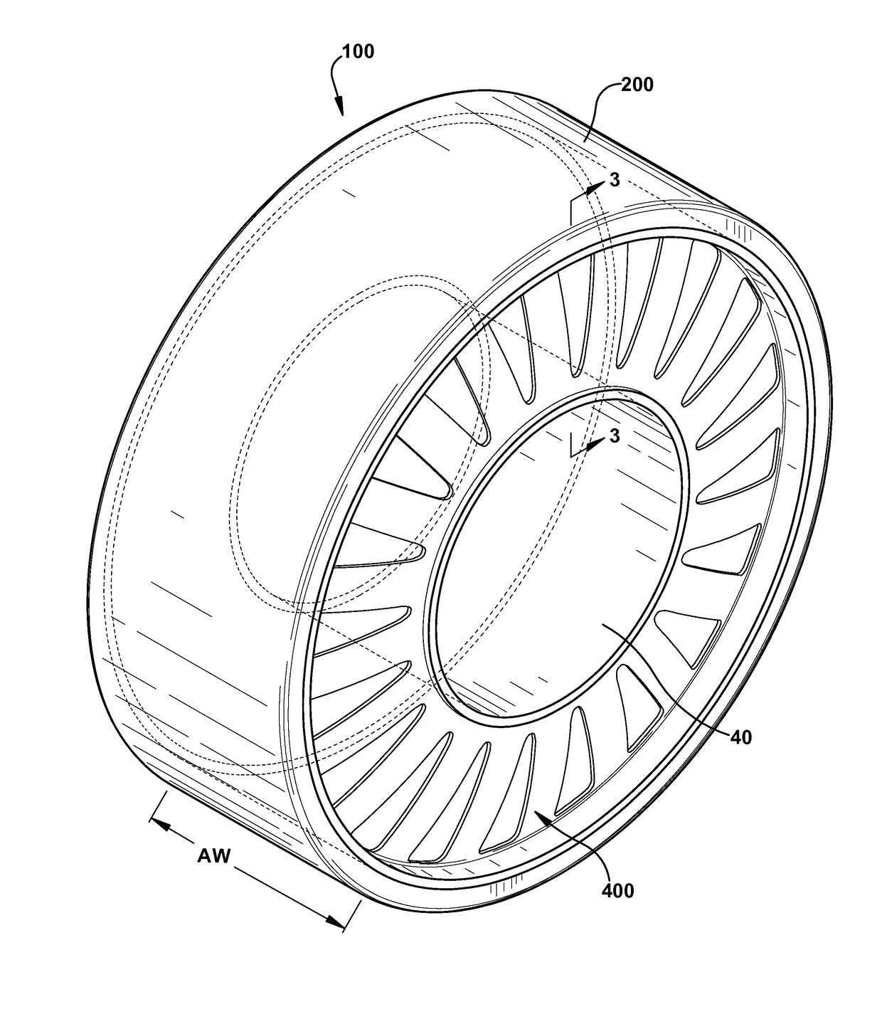
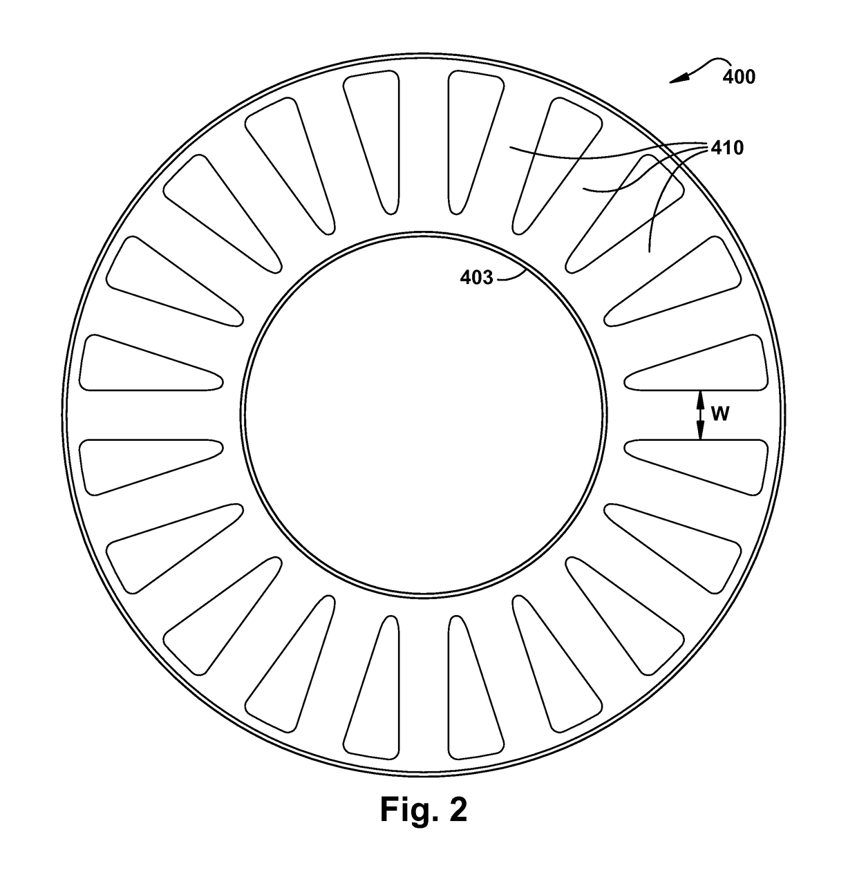
[0023]The non-pneumatic tire 100 of the present invention is shown in FIG. 1. The tire of the present invention includes a radially outer ground engaging tread 200, a shear band 300, and a spoke disk 400. The non-pneumatic tire of the present invention is designed to be a top loading structure, so that the shear band 300 and the connected spoke disks 400 efficiently carry the load. The shear band 300 and the connected spoke disks 400 are designed so that the stiffness of the shear band is directly related to the spring rate of the tire. The spoke disk is designed to be a stiff structure that buckles or deforms in the tire footprint and does not compress or carry a compressive load. This allows the rest of the spokes not in the footprint area the ability to carry the load. Since there are more spokes outside of the footprint than in, the load per spoke would be small, enabling smaller spokes to carry the tire load, resulting in a very load efficient structure. Not all spokes will be ...


PUM


Abstract

A structurally supported tire includes a ground contacting annular tread portion; a shear band, and a connected spoke disk connected to the shear band. The connected spoke disk has two or more circumferential spokes joined together by a connecting web, wherein the spring rate of the connected spoke disk is greater than the spring rate of the shear band.

Description

FIELD OF THE INVENTION[0001]The present invention relates generally to vehicle tires and non-pneumatic tires, and more particularly, to a non-pneumatic tire.BACKGROUND OF THE INVENTION[0002]The pneumatic tire has been the solution of choice for vehicular mobility for over a century. The pneumatic tire is a tensile structure. The pneumatic tire has at least four characteristics that make the pneumatic tire so dominate today. Pneumatic tires are efficient at carrying loads, because all of the tire structure is involved in carrying the load. Pneumatic tires are also desirable because they have low contact pressure, resulting in lower wear on roads due to the distribution of the load of the vehicle. Pneumatic tires also have low stiffness, which ensures a comfortable ride in a vehicle. The primary drawback to a pneumatic tire is that it requires compressed fluid. A conventional pneumatic tire is rendered useless after a complete loss of inflation pressure.[0003]A tire designed to operat...

Claims


Application Information

Patent Timeline
Patent Type & Authority Applications(United States)
IPC IPC(8): B60C7/14
CPCB60C2007/146B60C7/14B60B9/00B60C7/10B60C7/08B60C7/18B60C7/146B60C7/107B60B9/12B60B9/26B60B2900/115
Inventor SIEGEL, ADDISON BRIAN
Owner THE GOODYEAR TIRE & RUBBER CO
Why Eureka
Try Eureka