
Non-pneumatic tire

Active Publication Date: 2017-06-08
THE GOODYEAR TIRE & RUBBER CO
View PDF18 Cites 9 Cited by
  • Summary
  • Abstract
  • Description
  • Claims
  • Application Information

AI Technical Summary

Benefits of technology

The present invention relates to a non-pneumatic tire that can operate without inflation pressure. The non-pneumatic tire has the features of a pneumatic tire but without the drawbacks of requiring air inflation. The non-pneumatic tire is designed to carry the load efficiently, similar to a pneumatic tire, but without the need for air inflation. The non-pneumatic tire can provide the same performance as a pneumatic tire without the need for air inflation. The non-pneumatic tire is designed to address the issues and compromises associated with pneumatic tires, such as low efficiency, high maintenance costs, and environmental concerns. The non-pneumatic tire is a structural support tire that has a load carrying efficiency, stiffness, and comfort. The non-pneumatic tire can be designed to have the same performance as a pneumatic tire without the need for air inflation. The patent text describes various embodiments of the non-pneumatic tire and the methods for designing and testing them.

Problems solved by technology

The primary drawback to a pneumatic tire is that it requires compressed fluid.
A conventional pneumatic tire is rendered useless after a complete loss of inflation pressure.
Structurally supported tires such as solid tires or other elastomeric structures to date have not provided the levels of performance required from a conventional pneumatic tire.

Method used


Image

  • Non-pneumatic tire
  • Non-pneumatic tire
  • Non-pneumatic tire

Examples


fourth embodiment

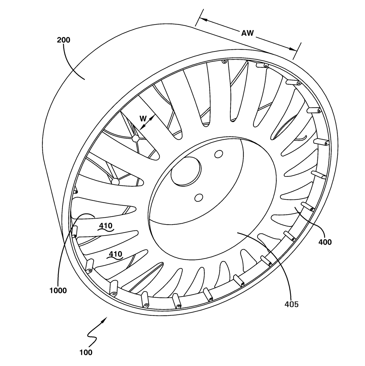
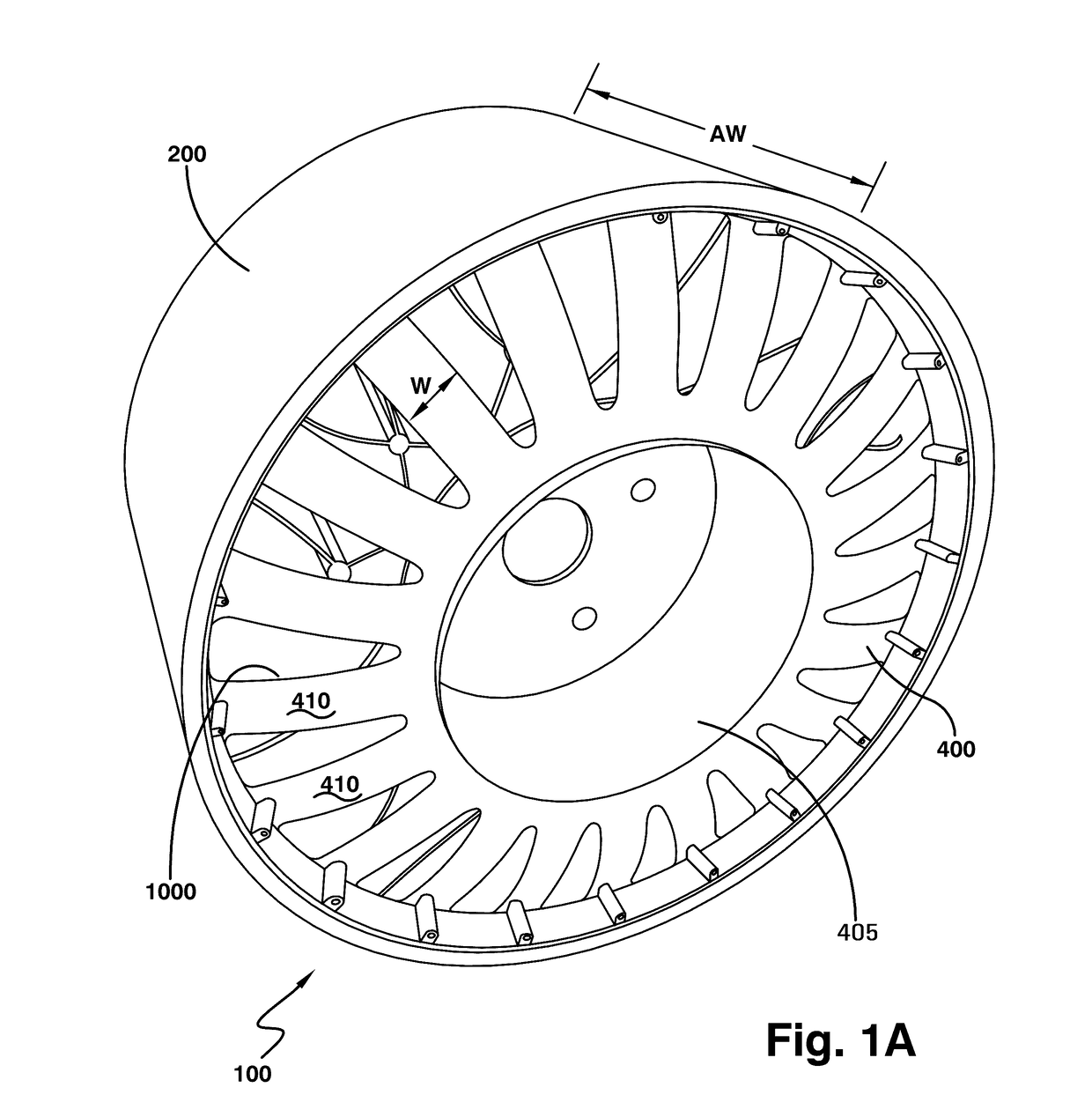
[0052]FIGS. 12-13 illustrates a spoke disk 1000. The spoke disk 1000 has an axial thickness A substantially less than the axial thickness AW of the non-pneumatic tire. The spoke disk 1000 has a plurality of spokes that connect an inner ring 1010 to an outer ring 1020. The shear band 300 is mounted radially outward of the spoke disks. The spoke disk 1000 has a first spoke 1030 that is linear and joins the outer ring 1020 to the inner ring 1010. The first spoke 1030 forms an angle Beta with the outer ring 1020 in the range of 20 to 80 degrees. Beta is preferably less than 90 degrees. The spoke disk 1000 further includes a second spoke 1040 that extends from the outer ring 1020 to the inner ring 1010, preferably in a curved shape. The second spoke 1040 is joined with the first spoke 1030 at a junction 1100. The curved spoke 1040 has a first curvature from the outer ring to the junction 1100, and a second curvature from the junction to the inner ring 1010. In this example, the first cur...

fifth embodiment

[0054]FIG. 14 illustrates a spoke disk 2000, which is similar to the spoke disk 1000, except for the following differences. The spoke disk 2000 has a first and second spoke 2030, 2040 which are joined together by a junction 2100, forming two approximate triangular shapes A,B, that have curved boundaries. Both the first and second spokes 2030,2040 extend from an outer ring 2020 to an inner ring 2010. Both the first and second spokes 2030, 2040 are curved. The curve of the outer radial portion L2 of each spoke has a first curvature, and the inner radial portions L1 have a curve in the opposite direction of the first curvature. FIG. 15 illustrates the spoke disk 2000 buckling under load. The radially outer portions of 2040,2030 buckle in the angular direction.

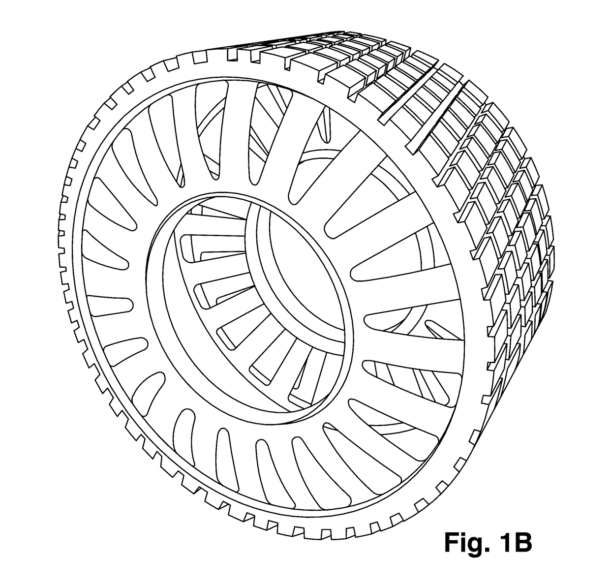
[0055]A preferred embodiment of a non-pneumatic tire is shown in FIG. 1B. The spoke disks on the outer axial ends are the spoke disks 400, and are oriented so that they buckle axially outward. Located between the opposed spoke dis...


PUM


Abstract

A structurally supported tire includes a ground contacting annular tread portion, an annular shear band and at least one spoke disk connected to the shear band, wherein the spoke disk has at least two spokes, wherein each spoke extends between an outer ring and an inner ring, wherein one of the spokes extends from the outer ring to the inner ring in a curved manner. The second spoke extends from the outer ring to the inner ring in a straight manner.

Description

FIELD OF THE INVENTION[0001]The present invention relates generally to vehicle tires and non-pneumatic tires, and more particularly, to a non-pneumatic tire.BACKGROUND OF THE INVENTION[0002]The pneumatic tire has been the solution of choice for vehicular mobility for over a century. The pneumatic tire is a tensile structure. The pneumatic tire has at least four characteristics that make the pneumatic tire so dominate today. Pneumatic tires are efficient at carrying loads, because all of the tire structure is involved in carrying the load. Pneumatic tires are also desirable because they have low contact pressure, resulting in lower wear on roads due to the distribution of the load of the vehicle. Pneumatic tires also have low stiffness, which ensures a comfortable ride in a vehicle. The primary drawback to a pneumatic tire is that it requires compressed fluid. A conventional pneumatic tire is rendered useless after a complete loss of inflation pressure.[0003]A tire designed to operat...

Claims


Application Information

Patent Timeline
IPC IPC(8): B60C7/14
CPCB60C2007/146B60C7/14B60C7/08B60C11/00B60C2200/00B60C7/146B60B3/002B60B2360/145B60C7/18B60C7/143
Inventor VAN RIPER, PHILIP CARLLETTIERI, JOSEPH CARMINEBANDY, REBECCA ANNESIEGEL, ADDISON BRIANMALEKZADEH MOGHANI, MAHDYMENDENHALL, ANDREW BRENT
Owner THE GOODYEAR TIRE & RUBBER CO
Learn More