Imaging device, imaging method, and program

a technology of imaging method and imaging device, which is applied in the field of imaging device (pan/tilt camera), imaging method, and program, can solve the problems of finger caught, pan/tilt camera misses the object to be tracked, and it is difficult to normally track objects, so as to prevent abnormal operations

Active Publication Date: 2017-06-08
FUJIFILM CORP
View PDF5 Cites 19 Cited by
  • Summary
  • Abstract
  • Description
  • Claims
  • Application Information

AI Technical Summary

Benefits of technology

[0037]According to the invention, in a case in which the physical amount detected by the motion sensor is equal to or greater than the first threshold value, the pan / tilt mechanism is stopped. Therefore, it is possible to provide an imaging device (pan / tilt camera), an imaging method, and a program that can prevent an abnormal operation such as hunting caused by abnormal automatic object tracking which is caused by the movement of the pan / tilt camera.

Problems solved by technology

In some cases, when the position or direction of a pan / tilt camera body is changed by external force (for example, is moved by the hand of a person) while a pan / tilt camera is automatically tracking an object, the pan / tilt camera misses the object, which makes it difficult to normally track the object.
In addition, when the position or direction of the pan / tilt camera body is changed by external force, the pan / tilt camera misses the object to be tracked.
As a result, a failure, such as hunting in which the pan / tilt camera repeatedly performs a pan operation and a tilt operation in order to search for the object, occurs or the problem that a finger is caught by the pan operation or the tilt operation arises.
However, JP2007-36661A to JP2011-138028A do not disclose a warning process or measures against a case in which a failure occurs in the automatic object tracking function of the pan / tilt camera.

Method used


Image

  • Imaging device, imaging method, and program
  • Imaging device, imaging method, and program
  • Imaging device, imaging method, and program

Examples


first embodiment

[0111]Next, a first embodiment of the invention will be described. In this embodiment, the operation of the pan / tilt mechanism 32 is controlled on the basis of the physical amount (hereinafter, referred to as, the “amount of movement”) related to the movement of the pan / tilt camera 10 and a “first threshold value” and a “first resumption threshold value” which will be described below.

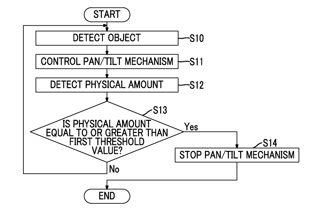
[0112]FIG. 5 is a flowchart illustrating the operation of the pan / tilt camera 10 according to this embodiment.

[0113]First, the object detection unit 65 detects an object to be tracked from a moving image captured by the imaging unit 20 (a object detection step: Step S10). Then, the pan / tilt control unit 44 controls the pan / tilt mechanism 32 such that the object detected by the object detection unit 65 is tracked (a pan / tilt control step: Step S11). Specifically, the pan / tilt control unit 44 controls the pan driving unit 34 and the tilt driving unit 36 such that the object detected by the object detectio...

modification example of first embodiment

[0121]Next, a modification example of the first embodiment will be described. In the modification example of the first embodiment, the first threshold value includes a threshold value in the pan direction and a threshold value in the tilt direction which is different from the threshold value in the pan direction.

[0122]The first threshold value may include a first horizontal direction threshold value which is related to the movement of the camera body in the horizontal direction (pan direction) and a first vertical direction threshold value which is related to the movement of the camera body in the vertical direction (tilt direction) and is different from the first horizontal direction threshold value. In a case in which the pan / tilt mechanism 32 is operated to track the object, the influence of movement in the pan direction on the tracking of the object is different from the influence of movement in the tilt direction on the tracking of the object. Therefore, different threshold val...

second embodiment

[0127]Next, a second embodiment of the invention will be described. In this embodiment, a moving image recording operation is controlled on the basis of the amount of movement of the pan / tilt camera 10 and a “second threshold value” and a “second resumption threshold value” which will be described below.

[0128]FIG. 8 is a flowchart illustrating the operation of the pan / tilt camera 10 according to this embodiment.

[0129]First, the object detection unit 65 detects an object to be tracked from a moving image captured by the imaging unit 20 (Step S30). Then, the pan / tilt control unit 44 controls the pan / tilt mechanism 32 such that the object detected by the object detection unit 65 is tracked (Step S31). The motion sensor 64 detects the amount of movement of the pan / tilt camera 10 (Step S32).

[0130]Then, in a case in which the amount of movement of the pan / tilt camera 10 detected by the motion sensor 64 is equal to or greater than the second threshold value (Yes in Step S33), the operation...


PUM


Abstract

An imaging device (pan/tilt camera) includes an imaging unit including an imaging lens and an imaging element, a pan/tilt mechanism that rotates the imaging unit in the horizontal direction and the vertical direction with respect to a camera body, an object detection unit that detects an object, which is a tracking target, from a moving image captured by the imaging unit, a pan/tilt control unit that controls the pan/tilt mechanism such that the object detected by the object detection unit is tracked, a motion sensor that detects a physical amount related to the movement of the camera body, and an operation control unit that stops the pan/tilt mechanism in a case in which the physical amount detected by the motion sensor is equal to or greater than a first threshold value.

Description

CROSS-REFERENCE TO RELATED APPLICATIONS[0001]This application is a Continuation of PCT International Application No. PCT / JP2015 / 068042 filed on Jun. 23, 2015, which claims priority under 35 U.S.C. §119(a) to Japanese Patent Application No. 2014-184166 filed on Sep. 10, 2014. Each of the above applications is hereby expressly incorporated by reference, in their entirety, into the present application.BACKGROUND OF THE INVENTION[0002]1. Field of the Invention[0003]The present invention relates to an imaging device (pan / tilt camera), an imaging method, and a program, and more particularly, to an imaging device (pan / tilt camera) having an automatic object tracking function, an imaging method using a pan / tilt camera, and a program.[0004]2. Description of the Related Art[0005]An imaging device (pan / tilt camera) provided with a pan / tilt mechanism can operate the pan / tilt mechanism to capture images in a wide range even in a case in which it is installed at a fixed point. Therefore, the pan / ...

Claims


Application Information

Patent Timeline
Patent Type & Authority Applications(United States)
IPC IPC(8): H04N5/232G06T7/246H04N5/77G06K9/00
CPCH04N5/23296H04N5/772G06T7/248G06K9/00744G03B15/00H04N7/18G03B37/02H04N5/77H04N7/183G03B2206/00G06T2207/10016G06T2207/30201G06T2207/30232G06T2207/30241G06T7/246H04N23/50H04N23/661H04N23/673H04N23/61H04N23/611H04N23/651H04N23/6815H04N23/685H04N23/632H04N23/69H04N23/695G06V20/46
Inventor IRIE, FUMINORITAMARU, MASAYAWATANABE, MIKIOMISAWA, TAKESHIHAYASHI, DAISUKEOSHIMA, HIROYUKI
Owner FUJIFILM CORP
Why Eureka
Try Eureka