Mask group and method for fabricating an organic luminescence layer, display panel and driving method

a luminescent layer and mask group technology, applied in the field of display technology, can solve the problems of deformation of grids, adverse effect of sub-pixel shapes to be fabricated, and degrade the brightness of color display,

Active Publication Date: 2017-06-22
BOE TECH GRP CO LTD +1
View PDF1 Cites 8 Cited by
  • Summary
  • Abstract
  • Description
  • Claims
  • Application Information

AI Technical Summary

Benefits of technology

[0024]According to the mask plate assembly provided by the disclosure, in comparison between the first mask plate and the second mask plate included in the mask plate assembly according to the disclosure and mask plates in the related arts, in a situation where sub-pixels are made to have a same width, a width of openings of both the first and second color mask plates as well as that of grids between the corresponding openings can be doubled, which can effectively prevent deforms at openings and grids therebetween from imposing bad influence on its performance, such that adverse effect on a shape of sub-pixels to be fabricated can be prevented as well.

Problems solved by technology

However, this method degrades displaying brightness for color displaying, due to the fact that a part of light rays are absorbed by the color filter.
Accordingly, within respective mask plates, a width of grids between respective openings (which is twice as that of openings, as shown in FIG. 1) need to be smaller, which may easily result in deform of grids and adverse effect on shapes of sub-pixels to be fabricated.

Method used


Image

  • Mask group and method for fabricating an organic luminescence layer, display panel and driving method
  • Mask group and method for fabricating an organic luminescence layer, display panel and driving method
  • Mask group and method for fabricating an organic luminescence layer, display panel and driving method

Examples


first embodiment

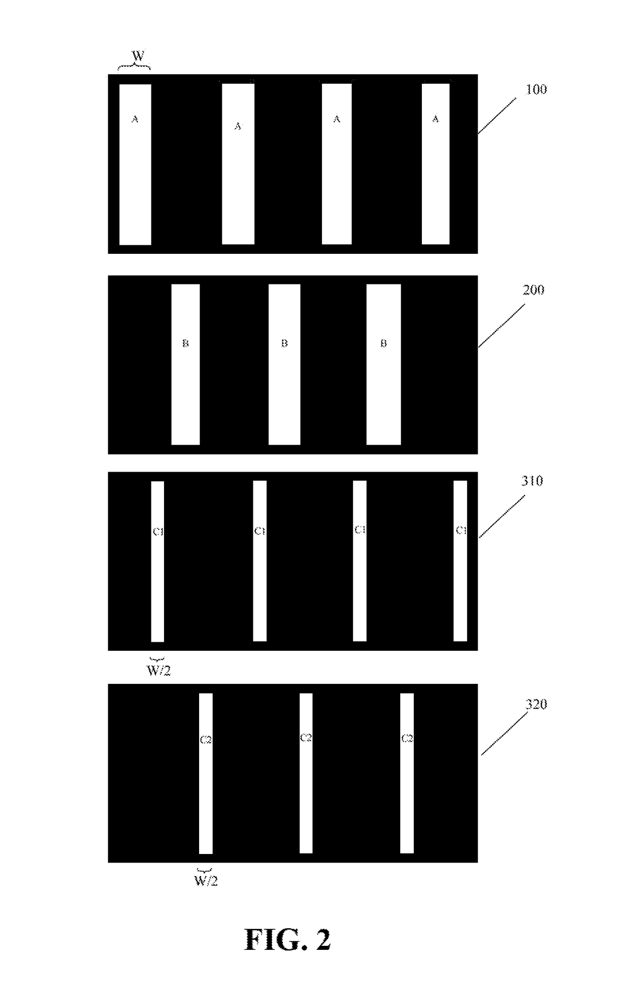
[0034]FIG. 2 is a schematic diagram illustrating a structure of a mask plate assembly according to the first embodiment of the disclosure. As shown in FIG. 2, the mask plate assembly includes a mask plate 100, a mask plate 200, a mask plate 310, and a mask plate 320. Each of the above mask plates includes a non-masking region and a masking region. Here the masking region is referred to as a region corresponding to a display region of a display panel to be fabricated, while the non-masking region is referred to as peripheral regions enclosing the masking region. Specifically, the masking region includes rectangular openings extended in a column direction and grids located between corresponding openings and used for defining rectangular openings. Further, a length of the rectangular openings is substantially the same as that of the masking region in the column direction.

[0035]Rectangular openings A of the mask plate 100 and rectangular openings B of the mask plate 200 are of a width o...

second embodiment

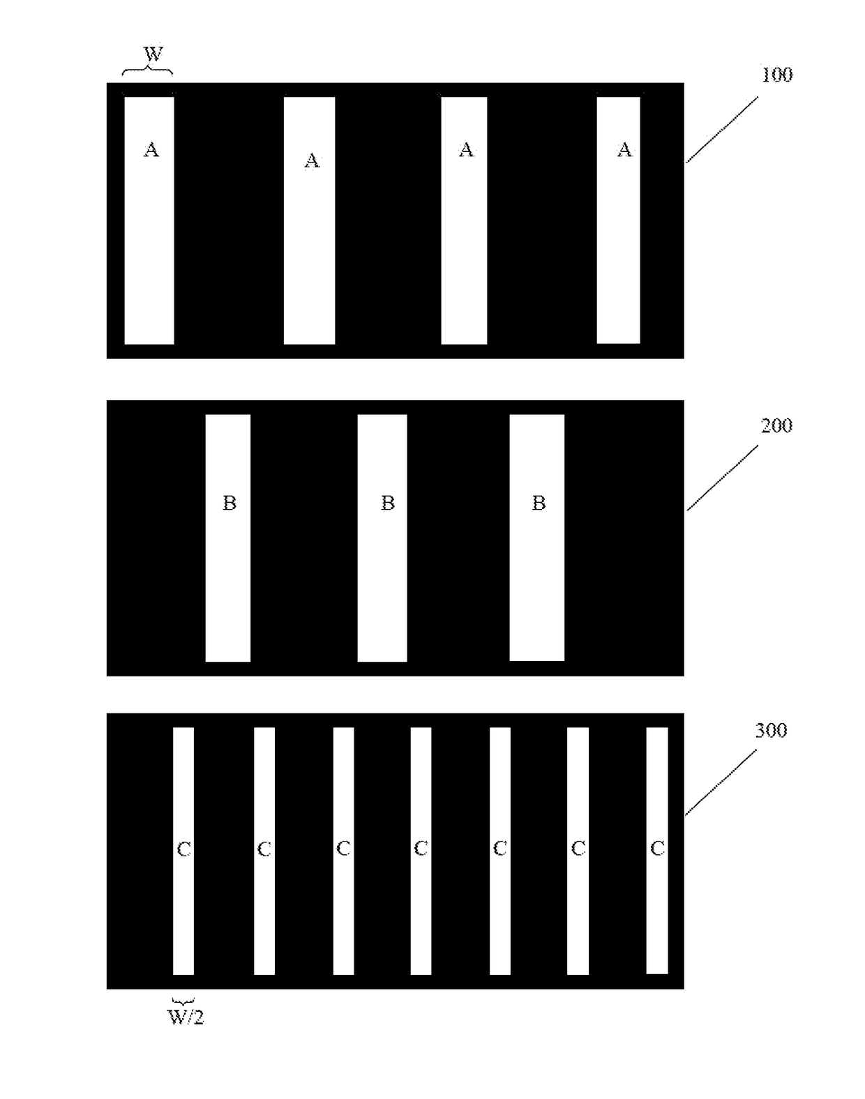
[0043]As different from the first embodiment, in the second embodiment, the mask plates 310 and 320 are replaced with one mask plate 300 having a plurality of rectangular openings C as shown in FIG. 4. When the mask plates 100, 200, and 300 are aligned with one another, in a row direction, the rectangular openings A, B, and C are arranged alternately in an order of a rectangular opening A, a rectangular opening C, a rectangular opening B, and another rectangular opening C.

[0044]The method for fabricating respective electroluminescent layers by using the mask plate assembly provided by the second embodiment may refer to that described in the first embodiment. The difference is that only one mask plate 300, other than two mask plates, is used for fabricating sub-pixels for displaying the third color.

[0045]The respective electroluminescent layers fabricated by using the mask plate assembly provided by the second embodiment may refer to FIG. 3, which will not be described in details.

[00...

third embodiment

[0047]As shown in FIG. 5, in the third embodiment, rectangular openings A of the mask plate 100 and rectangular openings B of the mask plate 200 are of a relatively smaller length, which is different from the first embodiment. When a plurality of rectangular openings A and a plurality of rectangular openings B are aligned in a column direction, then these openings A and B are arranged alternately. On the other hand, when the plurality of rectangular openings A and the plurality of rectangular openings B are aligned in a row direction, these openings A and B are also arranged alternately. Moreover, as in the first embodiment, both rectangular openings A and rectangular openings B are of a width twice as wide as that of rectangular openings C 1 and C2. Further, single rectangular opening A and single rectangular opening B are of a same length in the column direction, which is taken as L.

[0048]By comparing with the mask plates 100 and 200 in the related arts, grids of the mask plates 1...


PUM

PropertyMeasurementUnit
lengthaaaaaaaaaa
electroluminescentaaaaaaaaaa
colorsaaaaaaaaaa

Abstract

The disclosure provides a mask plate assembly, a method for fabricating an electroluminescent layer, a display panel and a method for driving the same. The mask plate assembly includes a first color mask plate, a second color mask plate, and a third color mask plate each having a plurality of rectangular openings. First openings of the first color mask plate and second openings of the second color mask plate are of a length in a row direction, which is substantially twice as that of third openings of the third color mask plate in the row direction. When the respective mask plates are aligned with one another, the first openings, the second openings, and the third openings are arranged alternately in an order of a first opening, a third opening, a second opening, and another third opening.

Description

CROSS REFERENCE TO RELATED APPLICATIONS[0001]This application is a National Stage entry of PCT / CN2016 / 070873 filed Jan. 14, 2016, which claims priority of Chinese Patent Application No. 201510446792.X, which was filed on Jul. 27, 2015, the disclosures of which are incorporated herein by reference in their entirety.BACKGROUND[0002]This disclosure relates to the field of display technology, in particular to a mask plate assembly, a method for fabricating an electroluminescent layer, a display panel and a method for driving the same.[0003]An Organic Light-Emitting Diode (OLED) display panel basically includes an anode, a light-emitting layer formed by organic electroluminescent materials, and a cathode.[0004]There are mainly two methods for achieving color displaying of OLED, one of which is to achieve color displaying by using a combination of a white-light organic electroluminescent material and a color filter. However, this method degrades displaying brightness for color displaying,...

Claims


Application Information

Patent Timeline
Patent Type & Authority Applications(United States)
IPC IPC(8): H01L51/56H01L27/32
CPCH01L51/56H01L2251/56H01L27/32H10K59/122H10K71/00C23C14/042H10K59/351H10K59/00H10K71/166
Inventor WU, HAIDONGLAI, WEILINBAI, JUANJUAN
Owner BOE TECH GRP CO LTD
Why Eureka
Try Eureka