Auto-locking ball joint

a ball joint and auto-locking technology, applied in the field of ball joints, can solve the problems of increasing the force of the external member exerted on the ball, difficult for a user to exert a large enough force, etc., and achieve the effect of increasing the locking force of the joint and increasing the locking ability of the auto-locking ball join

Inactive Publication Date: 2017-06-29
LEO D BERNSTEIN & SONS INC
View PDF38 Cites 12 Cited by
  • Summary
  • Abstract
  • Description
  • Claims
  • Application Information

AI Technical Summary

Benefits of technology

[0007]This disclosure relates generally to an auto-locking ball joint that is biased to a locked configuration where arms or links of the ball joint are fixed relative to one another. In the locked condition, the ball joint is configured to utilize forces on the links to increase the locking or fixing of the links relative to one another and acts as a self-actuating brake. As a self-actuating brake, the more force that is applied to move the ball joint the greater the locking force of the joint. The ball joint is transitioned to an unlocked condition by depressing one of the links towards the ball joint which allows the links of the ball joint to rotate in one or more degrees of freedom relative to one another. When the depressed link is released, the ball joint returns to the locked condition. It is envisioned that the force required to depress the link is relatively small compared to the forces experienced by the link in directions other than towards the ball joint to unlock the ball joint.
[0010]In some aspects, the plurality of segments of the ball define a first gap between adjacent segments in the locked configuration and define a second gap between adjacent segments in the unlocked configuration where the second gap is smaller than the first gap. In the unlocked configuration, the second gap may be substantially zero such that adjacent segments are in contact with one another. The first end portion of the second elongate member may include flats and edges that are defined at the intersection of adjacent flats. The edge of the first end portion may be disposed in a gap between adjacent segments of the ball such that rotation of the second elongate member engages the edge with one of the adjacent segments to move the ball segment outward and into engagement with the inner surface defining the well of the receiver. The geometry of the auto-locking ball joint may be designed such that rotation of the second elongate member increases the locking force of the joint. In addition, the more force applied to rotate the second elongate member may increase the locking ability of the auto-locking ball joint.

Problems solved by technology

One limitation of this type of locking member is that when a force is applied to one of the links to move the links relative to one another about the locked ball joint, the force of the external member exerted on the ball must be increased or be greater than the force applied to the links.
It can be difficult for a user to exert a large enough force with the external member on the ball to lock the ball joint when a large force is applied to one of the links to move the links relative to one another.

Method used


Image

  • Auto-locking ball joint
  • Auto-locking ball joint
  • Auto-locking ball joint

Examples


Embodiment Construction

[0034]Embodiments of the present disclosure are now described in detail with reference to the drawings in which like reference numerals designate identical or corresponding elements in each of the several views.

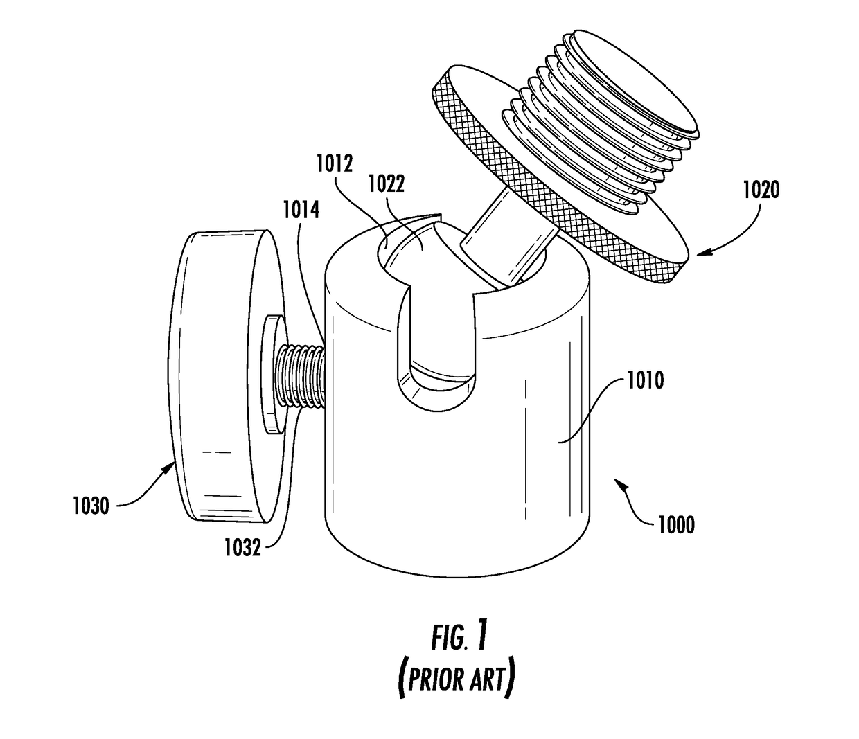
[0035]Typically, prior art locking ball joints use frictional engagement of a locking member to frictionally engage a ball and to urge the ball into frictional engagement with a portion of the ball joint. For example with reference to FIG. 1, a prior art locking ball joint 1000 is shown including a collar 1010, a ball end 1020, and a locking handle 1030. The collar 1010 defines a recess 1012 and a lock opening 1014. The ball end 1020 includes a ball 1022 that is rotatably disposed within the recess 1012 of the collar 1010. The locking handle 1030 includes a locking member 1032 that extends through the lock opening 1014 of the locking collar 1010 to engage the ball 1022. The engagement of the locking member 1032 and the ball 1022 locks ball end 1020 relative to the collar 1010...


PUM


Abstract

An auto-locking ball joint includes a first elongate member, a ball, and a second elongate member. The first elongate member includes a receiver disposed at one end. The receiver has an inner surface that defines a well. The ball is rotatable disposed within the well. The ball is formed from a plurality of segments that are moveable relative to one another towards and away from a ball axis. The second elongate member is translatable along the ball axis. In a locked configuration, the outer surface of the ball frictionally engages the inner surface to prevent the ball from rotating within the well. In an unlocked configuration of the ball joint, the ball is rotatable within the well. The second elongate member is depressed along the ball axis to transition the ball joint from locked configuration to the unlocked configuration.

Description

BACKGROUND[0001]1. Technical Field[0002]The present disclosure relates to ball joints and, more specifically, to ball joints including an auto-locking mechanism.[0003]2. Discussion of Related Art[0004]Ball joints allow two links to be coupled together while permitting rotation of the links about the joint in all three rotational degrees of freedom (DOF). Some ball joints include a locking mechanism that allow the ball joint to be locked to fix the links to one another in one or more of the DOF.[0005]Typically, a locking mechanism includes an external member that is moved into contact with a ball of the ball joint such that engagement of the external member and the ball locks the ball joint. One limitation of this type of locking member is that when a force is applied to one of the links to move the links relative to one another about the locked ball joint, the force of the external member exerted on the ball must be increased or be greater than the force applied to the links. It can...

Claims


Application Information

Patent Timeline
Patent Type & Authority Applications(United States)
IPC IPC(8): F16C11/06A47F8/02
CPCA47F8/02F16C11/0604F16C2316/30A47F8/00F16C11/106
Inventor SUTTON, LEVI
Owner LEO D BERNSTEIN & SONS INC
Why Eureka
Try Eureka