Luminaire, especially for road lighting

a technology for road lighting and luminaires, applied in semiconductor devices, light sources, fixed installations, etc., can solve the problems of complicated design and manufacture of optical plates, limited light intensity that can shine directly into drivers eyes, and dangerous glare for drivers, etc., to achieve simple design and manufacture

Active Publication Date: 2017-06-29
SIGNIFY HLDG BV
View PDF2 Cites 0 Cited by
  • Summary
  • Abstract
  • Description
  • Claims
  • Application Information

AI Technical Summary

Benefits of technology

[0016]In this arrangement, a reflector performs a light redirection function perpendicular to the road direction whereas the optical plate principally redirects light in the direction of the road, because it is formed of side-to-side elongate prisms. This allows the optical plate to be simpler to design, with the shape of the prismatic element varying only in one dimension. This can result in an optical plate that is cheaper to manufacture, for example by extrusion, embossing or other conventional techniques.
[0017]The optical plate may have a design which can be independent of the luminaire source dimension (i.e. the entrance window direction) in the direction of the road and the height of the reflector. The prisms facing with an upper face towards the light source instead of with the upright face enables less sharp facets, thus reducing the risk on damage to the prisms. Furthermore, it surprisingly appeared possible to obtain the desired light distribution via refraction (possibly in combination with TIR) in only one step, i.e. each light ray only propagates through only one (respective) optical plate via a single (respective) optical element on said optical plate. The specific design of the reflector in combination with the specific design of the optical plate enabled a further tweaking of the desired light distribution.
[0019]The opposite sides and the opposite ends may be planar. This provides a simple to design and manufacture reflector.
[0024]The prism angle γ increases from the central prism for an inner section of the optical plate extending outwardly from the center, and the prism angle decreases for an outer section of the optical plate extending outwardly to the outer edge. Thus, the prisms may have a specific angle γ with respect to the vertical (i.e. the normal to the optical plate) that is a one dimensional function with respect to the dimension of the plate in the direction of the road. This provides a design which is simple to design and manufacture.

Problems solved by technology

Moreover, it is required that the intensity of the light that can shine directly into a driver's eyes is limited.
Too much light that shines directly into the driver's eyes leads to glare which can be dangerous for a driver.
The design and manufacture of the optical plate can however be complicated.

Method used


Image

  • Luminaire, especially for road lighting
  • Luminaire, especially for road lighting
  • Luminaire, especially for road lighting

Examples


Embodiment Construction

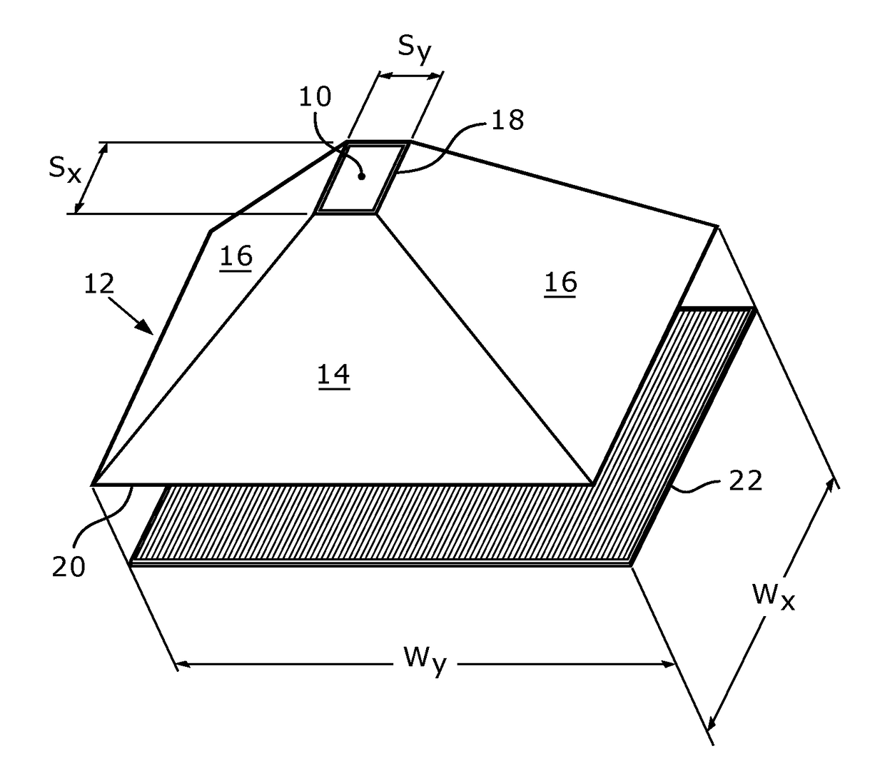
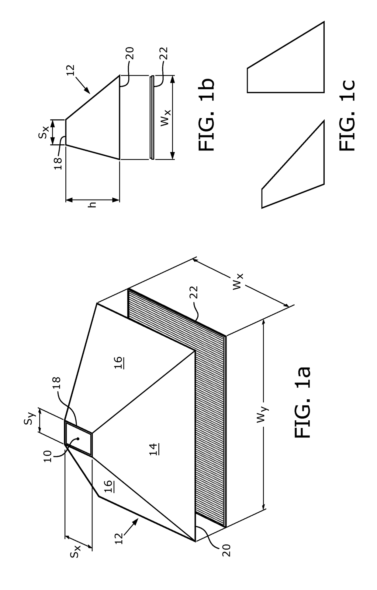
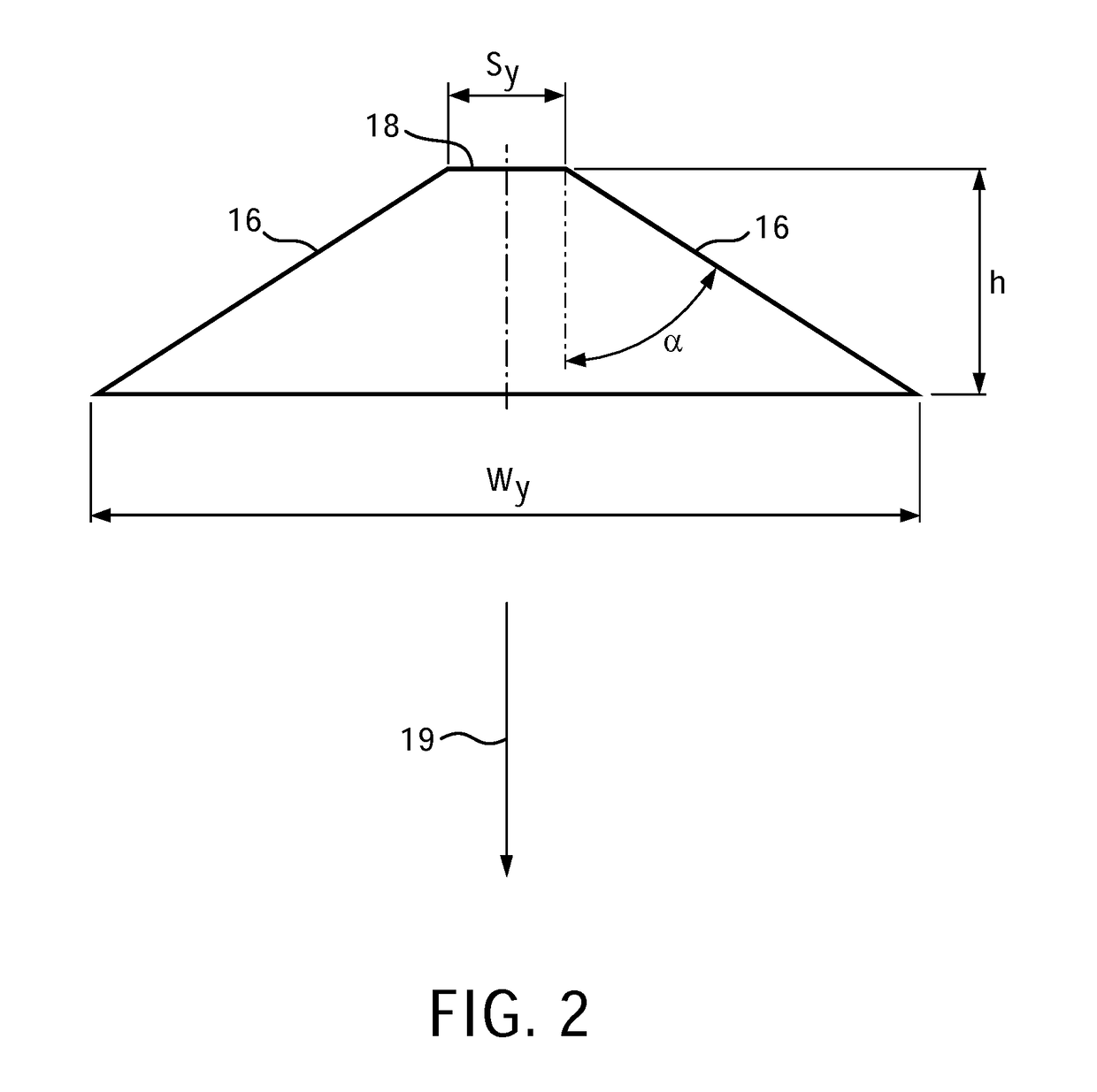
[0043]The invention provides a luminaire for illuminating a road, comprising a light source, a reflector arrangement defining a light entrance window at the top to which light is supplied by the light source and a larger light exit window at the bottom, and an optical plate over the light exit window. The optical plate comprises an array of elongate prisms which each extend in a side-to-side direction corresponding to the width direction of the road. The reflector is primarily responsible for control of the light output in the road width direction and the optical plate is primarily responsible for control of the light output in the road length direction.

[0044]A luminaire in accordance with an embodiment is shown in FIG. 1. FIG. 1(a) is a perspective view and FIG. 1(b) is view of one end, looking along the direction of the road.

[0045]The luminaire comprises a light source 10, and a reflector arrangement 12 having opposite sides 14 and opposite ends 16, and defining a light entrance w...


PUM


Abstract

The invention provides a luminaire for illuminating a road, comprising a light source (10), a reflector arrangement (12) defining a light entrance window (18) at the top to which light is supplied by the light source (10) and a larger light exit window (20) at the bottom, and an optical plate (22) over the light exit window (20). The optical plate (22) comprises an array of elongate prisms which each extend in a side-to-side direction corresponding to the width direction of the road. The reflector (12) is primarily responsible for control of the light output in the road width direction and the optical plate (22) is primarily responsible for control of the light output in the road length direction.

Description

FIELD OF THE INVENTION[0001]This invention relates to luminaries for road lighting.BACKGROUND OF THE INVENTION[0002]Road luminaires are designed such that a certain luminance from the road is achieved with a required uniformity according to governmental specifications.[0003]These specifications are particularly demanding in respect of the uniformity of the luminance in the direction of the road that the driver encounters in a particular lane. Moreover, it is required that the intensity of the light that can shine directly into a driver's eyes is limited. Too much light that shines directly into the driver's eyes leads to glare which can be dangerous for a driver. Thus, there is a careful balance in the light distribution for a road luminaire in the direction of the road that achieves the required uniformity and keeps the glare within the required specifications.[0004]The preferred light source now used in road luminaires is a light emitting diode (LED) (in practice an array thereof)...

Claims


Application Information

Patent Timeline
Patent Type & Authority Applications(United States)
IPC IPC(8): F21S8/08F21V13/04F21V7/10F21V5/02F21V7/05
CPCF21S8/086F21V5/02F21W2131/103F21V7/10F21V13/04F21V7/05F21Y2105/10F21Y2115/10
Inventor VREDENBORG, ARNO
Owner SIGNIFY HLDG BV
Why Eureka
Try Eureka