Luminance controller and organic light emitting display device having the same

a technology of light emitting display device and controller, which is applied in the direction of instruments, static indicating devices, etc., can solve the problems of color shift, light emission is often delayed in a low luminance, and differences in luminance efficiency of red/, so as to reduce or minimize the light emission delay caused by bcb operation, light emission delay may be reduced or reduced, and light emission delay may be improved

Active Publication Date: 2017-06-29
SAMSUNG DISPLAY CO LTD
View PDF6 Cites 33 Cited by
  • Summary
  • Abstract
  • Description
  • Claims
  • Application Information

AI Technical Summary

Benefits of technology

[0028]Therefore, the luminance controller according to example embodiments may control the target initialization voltage and the target common voltage, that correspond to the selected gamma set, based on change in the target luminance. Thus, a voltage difference between the target initialization voltage and the target common voltage may be reduced or minimized when a black current bypass (BCB) operation of the pixel is performed, so that a light emission delay caused by the BCB operation may be reduced or minimized. Particularly, a voltage for the BCB operation may be moved closer to a threshold voltage of the organic light emitting diode when a low driving current display such as a low luminance display and / or a low grayscale display is performed, so that the light emission delay may be reduced.
[0029]In addition, the organic light emitting display device may include a luminance controller such that the light emission delay may be improved without a change of optical characteristics. Further, a color shift may be eliminated or reduced in the low luminance (low gray scale) range.

Problems solved by technology

However, in using this method, light emission is often delayed in a low luminance (and / or a low grayscale) range by parasitic elements of the organic light emitting diode such as a parasitic capacitance, etc.
In addition, a color shift occurs due to differences of luminance efficiency of red / green / blue pixels.

Method used


Image

  • Luminance controller and organic light emitting display device having the same
  • Luminance controller and organic light emitting display device having the same
  • Luminance controller and organic light emitting display device having the same

Examples


Embodiment Construction

[0040]Exemplary embodiments will be described more fully hereinafter with reference to the accompanying drawings, in which various embodiments are shown. The drawings may not be to scale. All numerical values are approximate, and may vary. All examples of specific materials and compositions are to be taken as nonlimiting and exemplary only. Other suitable materials and compositions may be used instead.

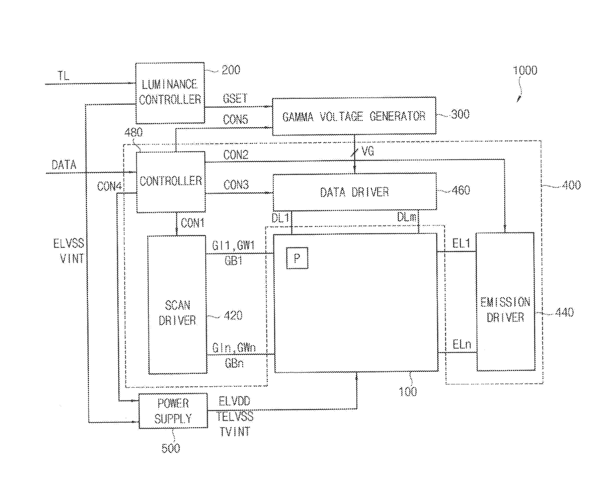
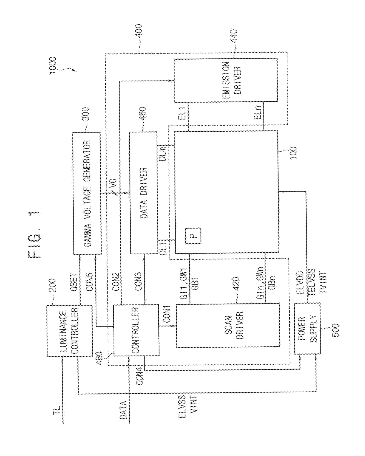
[0041]FIG. 1 is a block diagram of an organic light emitting display device constructed according to example embodiments.

[0042]Referring to FIG. 1, the organic light emitting display device 1000 may include a display panel 100, a luminance controller 200, a gamma voltage generator 300, a display panel driver 400, and a power supply 500. In one embodiment, the display panel driver 400 may include a scan driver 420, an emission driver 440, a data driver 460, and a controller 480.

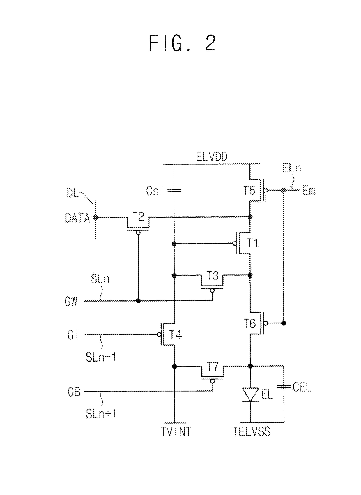
[0043]The display panel 100 may include a plurality of pixels P, and may display images. The display panel 100...


PUM


Abstract

A luminance controller according to example embodiments includes a gamma set selector to select a reference gamma set from among first through N-th gamma sets respectively corresponding to first through N-th reference luminances, based on a target luminance of a display panel; an initialization voltage selector to select an initialization voltage corresponding to the reference gamma set, from among first through N-th initialization voltage offsets respectively corresponding to the first through N-th gamma sets; a common voltage selector to select a common voltage corresponding to the reference gamma set from among first through N-th common voltage offsets respectively corresponding to the first through N-th gamma sets; and a determiner to determine a target initialization voltage based on the target luminance and the initialization voltage, and to determine a target common voltage based on the target luminance and the common voltage.

Description

CROSS REFERENCE TO RELATED APPLICATION[0001]This application claims priority to, and the benefit of, Korean Patent Application No. 10-2015-0188326 filed on Dec. 29, 2015 in the Korean Intellectual Property Office (KIPO), the disclosure of which is hereby incorporated by reference herein in its entirety.BACKGROUND[0002]1. Field[0003]Example embodiments of the inventive concept relate generally to display devices. More particularly, example embodiments of the inventive concept relate to luminance controllers and organic light emitting display devices having the same.[0004]2. Discussion of Related Art[0005]A black current bypass (BCB) driving method initializes an organic light emitting diode by providing an initialization voltage (e.g., VINT voltage) to an anode of the organic light emitting diode. BCB driving is used to drive a pixel to improve black luminance performance (or black image performance). However, in using this method, light emission is often delayed in a low luminance (...

Claims


Application Information

Patent Timeline
Patent Type & Authority Applications(United States)
IPC IPC(8): G09G3/3258
CPCG09G2320/0626G09G3/3258G09G3/3233G09G2300/0814G09G2300/0819G09G2300/0871G09G2320/0673G09G2330/028
Inventor JUNG, YEON-SHILKIM, YOUNG-SEOBSON, JI-YUNOH, EUN-JUNGCHOI, DEOK-JUN
Owner SAMSUNG DISPLAY CO LTD
Why Eureka
Try Eureka