
Tabletop vaporizer

a vaporizer and tabletop technology, applied in the field of vaporizers on the tabletop, can solve the problems of unwieldy process, ineffective process, and harmful substances to health,

Active Publication Date: 2017-07-06
MONTGOMERY ADAM
View PDF4 Cites 37 Cited by
  • Summary
  • Abstract
  • Description
  • Claims
  • Application Information

AI Technical Summary

Benefits of technology

The invention is a vaporizer that uses heat to vaporize solid or liquid carrier materials. It includes a support member and an air heating assembly. The assembly has a radiating element and a chamber element. The radiating element has a central tubular member and upper and lower walls that create an air chamber therebetween. The chamber element encircling the radiating element has at least one aperture in gaseous communication with the air chamber. A heating element is carried within the radiating element, and a hand piece is attached to the exit aperture of the chamber element. The vaporizer also includes a flexible tubing and a mouthpiece. The vaporizing chamber assembly contains a receptacle with a coupling member and a screen holder with a screen. The screen is retained in position by the screen holder and is carried by the vaporizer. The technical effects of this invention are a more efficient and effective vaporizer for carrier materials with improved air flow and reduced smoke and odor production.

Problems solved by technology

While very effective, there are drawbacks to this process.
These combustion substances can be detrimental to health and add unpleasantness to the process.
While eliminating combustion products, this process can be unwieldy and very inefficient.
Unfortunately, these devices are limited in the type of carrier material which can be used.
Only solids can be vaporized in the conventional devices, greatly limiting their effectiveness.
Additionally, controlled heating of the carrier material can be problematic, causing burning as opposed to vaporization

Method used


Image

  • Tabletop vaporizer
  • Tabletop vaporizer
  • Tabletop vaporizer

Examples


Embodiment Construction

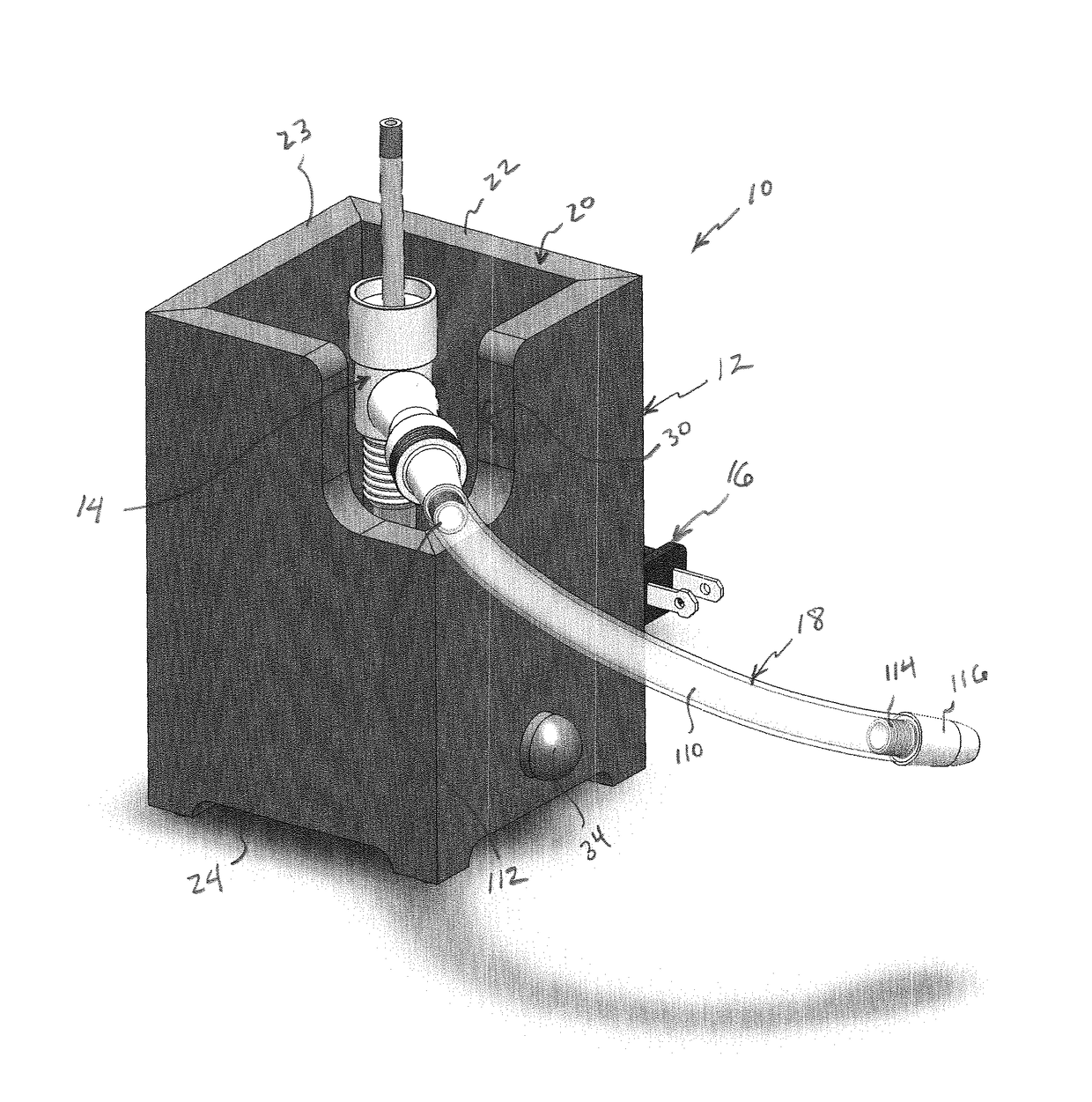
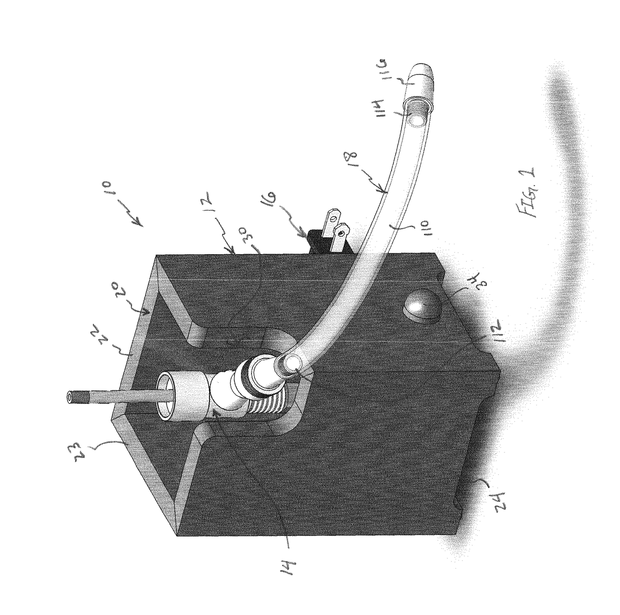
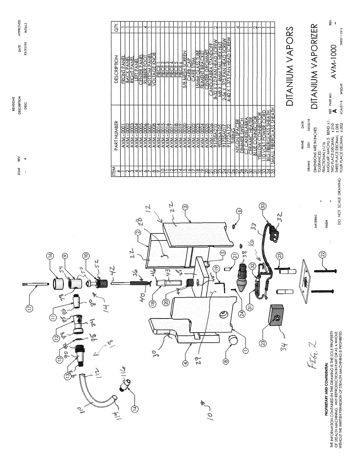
[0018]Turning now to the drawings in which like reference characters indicate corresponding elements throughout the several views, attention is first directed to FIGS. 1 and 2 which illustrate a tabletop vaporizer generally designated 10, for vaporizing the active ingredients of plant material, commonly cannabis, tobacco, or other herbs or blends for the purpose of inhalation, as well as essential oils or liquids containing active components, herein referred to as carrier material. It will also be understood that pure chemicals when mixed with plant material can also be used as a carrier material. Vaporizer 10 includes a housing 12 supporting a vaporizing mechanism 14 controlled by an electrical system 16 on a generally flat surface such as a table, desk, floor and the like. For purposes of this description, the terms “upper” and “lower” are used to designate the orientation of elements away from the surface and toward the surface respectively. Vapor is generated through a hand piec...


PUM


Abstract

A vaporizer for thermally vaporizing solid or liquid carrier materials is taught. The vaporizer includes a support member, and an air heating assembly carried by the support member. The air heating assembly includes a radiating element having a central tubular member with an upper end wall defining a reservoir for liquid carrier materials and a lower end wall spaced apart from the upper end wall defining an air chamber therebetween. A chamber element is received about the radiating element to close the air chamber and direct airflow therethrough. A heating element is carried within the tubular member of the radiating element. A hand piece including a vaporization chamber is couplable to an exit aperture of the chamber element.

Description

FIELD OF THE INVENTION[0001]This invention relates to devices for vaporizing substances from carrier materials. More particularly, the present invention relates to desktop vaporizers employing thermal vaporization.BACKGROUND OF THE INVENTION[0002]The drawing of substances into the lungs of an individual has long occurred for medical, religious and recreational reasons. Conventionally, drawing substances into the lungs has occurred primarily by the combustion of carrier materials to produce smoke, which is then inhaled into the lungs. This process has been used for a long time, and has been developed to include many devices to assist combustion and inhalation. While very effective, there are drawbacks to this process. Primarily, along with the substance desired, other products of the combustion process are also drawn into the lungs. These combustion substances can be detrimental to health and add unpleasantness to the process.[0003]Another method of introducing substances into the lu...

Claims


Application Information

Patent Timeline
Patent Type & Authority Applications(United States)
IPC IPC(8): A24F47/00H05B1/02F22B1/28A24F40/10A24F40/20A24F40/30A24F40/46A24F40/485
CPCA24F47/008H05B1/0297F22B1/284H05B3/04H05B3/141H05B3/44H05B2203/014H05B2203/021H05B2203/022A24F40/46A24F40/10A24F40/30A24F40/20A24F40/485
Inventor MONTGOMERY, ADAM
Owner MONTGOMERY ADAM
Learn More