Range determination device for automatic transmission

Active Publication Date: 2017-07-13
MAZDA MOTOR CORP
View PDF6 Cites 2 Cited by
  • Summary
  • Abstract
  • Description
  • Claims
  • Application Information

AI Technical Summary

Benefits of technology

[0005]In view of the above, an object of the present invention is to provide a range determination device for an

Problems solved by technology

In an actual automatic transmission, however, a frictional engagement element may not be operated as intended by a hydraulic pattern due to a defect of a hydraulic circuit or a frictional engagement element.
In this case, if a range is determined on the basis of hydraulic pattern of a frictional engage

Method used


Image

  • Range determination device for automatic transmission
  • Range determination device for automatic transmission
  • Range determination device for automatic transmission

Examples


Example

[0017]In the following, a preferred embodiment of an automatic transmission to which a range determination device of the present invention is applied is described in detail referring to the drawings.

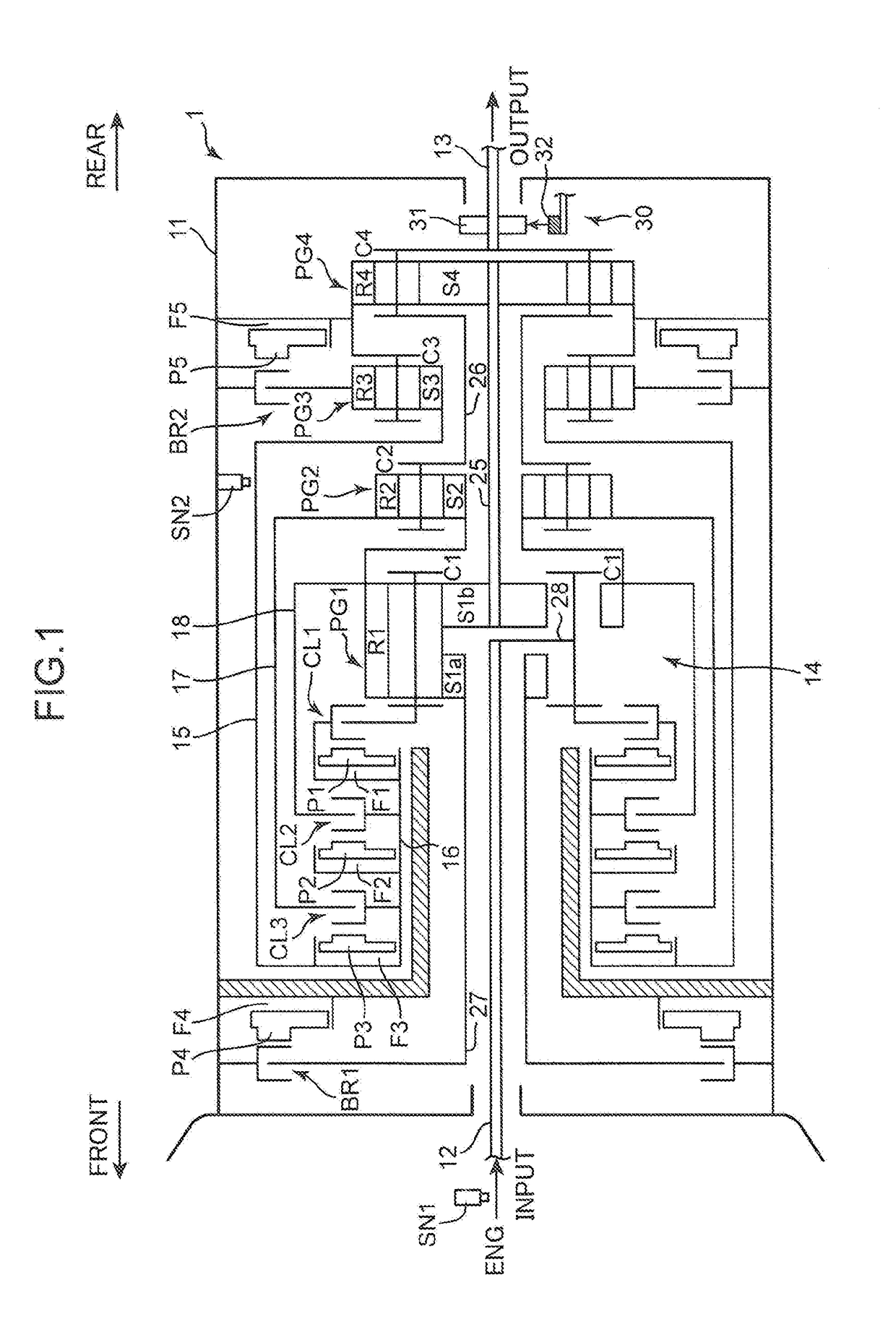
(1) Overall Configuration of Automatic Transmission

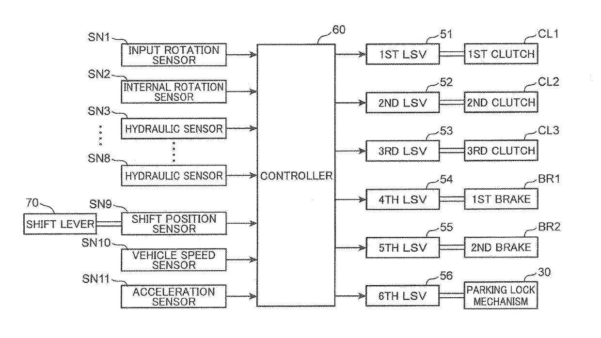
[0018]FIG. 1 is a conceptual diagram schematically illustrating an overall configuration of an automatic transmission 1 according to an embodiment of the present invention. The automatic transmission 1 is mounted in a vehicle such as an automobile for transmitting a driving force to be input from an engine (not illustrated) as a power source to wheels while shifting a gear position. Specifically, the automatic transmission 1 includes an input shaft 12 (corresponding to an input portion in the claims), which is driven to rotate by the engine, an output shaft 13 (corresponding to an output portion in the claims) coaxially disposed with the input shaft 12 on the side opposite to the engine, a transmission mechanism 14 (corresponding to a ra...


PUM


Abstract

A range determination device is applied to an automatic transmission provided with an input portion, an output portion, and a range switching mechanism which transmits rotation of the input portion to the output portion, and which is operative to switch the range of the automatic transmission between a forward range and a reverse range, in which directions of transmitting rotation from the input portion to the output portion are different from each other. The range determination device includes a rotational state detection unit which detects a rotational state of a predetermined rotary member included in the range switching mechanism, and a determination unit which determines that the forward range or the reverse range is attained on the basis of the rotational state of the rotary member detected by the rotational state detection unit.

Description

FIELD OF THE INVENTION[0001]The present invention relates to a technique for determining a range of an automatic transmission including an input portion and an output portion, and a range switching mechanism which transmits rotation of the input portion to the output portion, and which is operative to switch the range of the automatic transmission between a forward range and a reverse range, in which directions of transmitting rotation from the input portion to the output portion are different from each other.BACKGROUND ART[0002]Generally, an automatic transmission includes a plurality of planetary gear sets, and a plurality of hydraulically driven frictional engagement elements (clutches and brakes) for switching a power transmission path by each of the planetary gear sets. Further, various ranges such as a forward range and a reverse range are attained by selective engagement of a specific one of the frictional engagement elements.[0003]In particular, in an automatic transmission ...

Claims


Application Information

Patent Timeline
IPC IPC(8): F16H59/68F16H61/30
CPCF16H59/68F16H61/30F16H3/663F16H2200/006F16H2059/6823F16H2200/2043F16H2059/683F16H2059/708F16H2200/2012F16H61/00F16H59/36F16H59/44F16H59/54F16H2059/443F16H2059/6807F16H61/36
Inventor SAWA, KENJIKIMURA, TAKAHIRO
Owner MAZDA MOTOR CORP
Why Eureka
Try Eureka