
Method to manufacture an electric machine, installation, vehicle

Pending Publication Date: 2022-03-03
SIEMENS AG
View PDF2 Cites 0 Cited by
  • Summary
  • Abstract
  • Description
  • Claims
  • Application Information

AI Technical Summary

Benefits of technology

The patent is about a new method for making electric machines using ceramic particles to keep the magnetic laminations separate from each other. This makes it easier to insulate the magnetic laminations, and the ceramic particles also act as sintering inhibitors to prevent the laminations from fusing together. The ceramic particles used are spherical, whisker-shaped, or platelet-shaped with a maximum diameter of 5 micrometers. This method simplifies the manufacturing process and reduces costs.

Problems solved by technology

The manufacturing steps required for this, for example transport, storage, fitting and removal, for such a high number of individual components during the thermal processing and the separate after-treatment thereof are complex and expensive.

Method used


Image

  • Method to manufacture an electric machine, installation, vehicle
  • Method to manufacture an electric machine, installation, vehicle
  • Method to manufacture an electric machine, installation, vehicle

Examples


Embodiment Construction

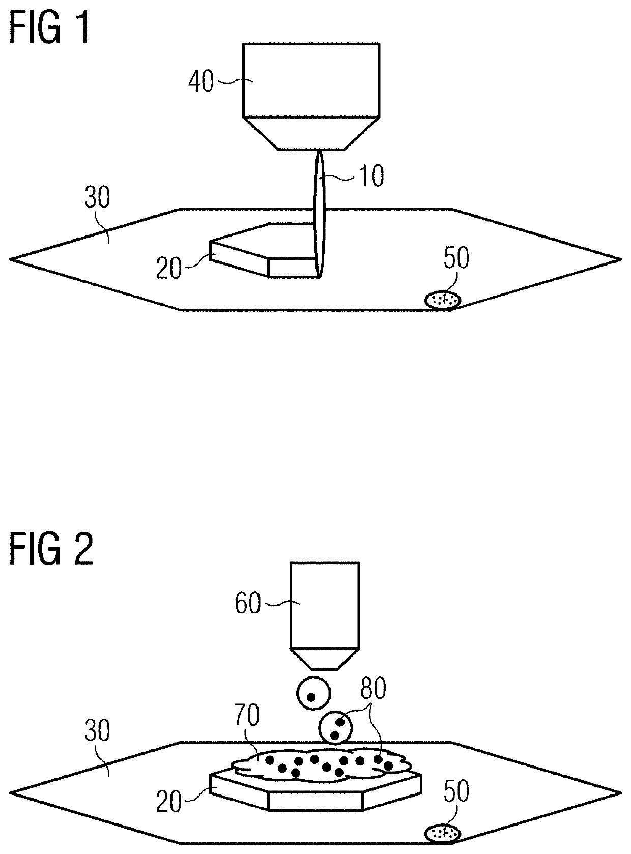
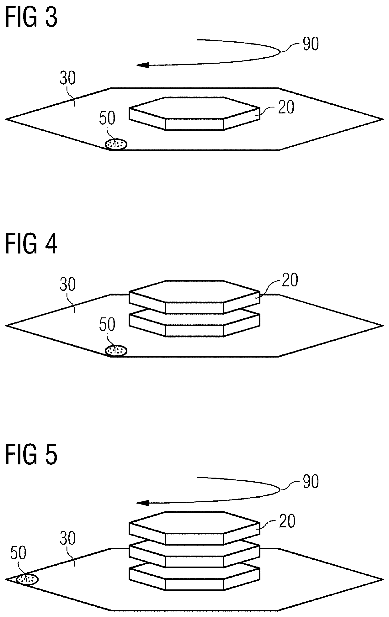
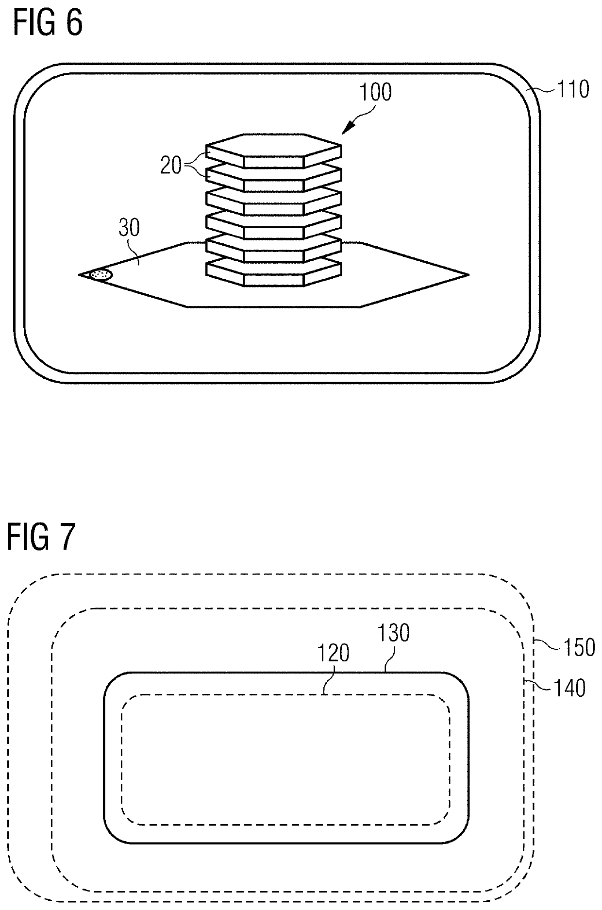
[0034]The method shown in FIGS. 1 to 7 is a method for manufacturing an electric machine including a stack of magnetic laminations.

[0035]In the method, the magnetic laminations are printed in a screen-printing method by stencil printing. To that end, in the method firstly a printing paste 10 is produced from metal powders, in the embodiment illustrated from pure iron powders. A first green body 20 is printed onto a substrate 30 by the printing paste 10.

[0036]The green body 20 should form a magnetic lamination after a sintering step, explained in more detail below, and has the form of a thin layer on the substrate 30, with the result that the green body 20 has a lower flat side, with which it makes contact with the substrate 30, and an upper flat side, that faces away from the lower flat side and extends parallel thereto.

[0037]In order to print the green body 20, a printing screen (not illustrated explicitly in the drawing) with a stencil (not illustrated explicitly in the drawing) i...


PUM

PropertyMeasurementUnit
Fractionaaaaaaaaaa
Angleaaaaaaaaaa
Magnetismaaaaaaaaaa

Abstract

A method for manufacturing an electric machine having a stack of magnetic laminations including a stack of green blanks. A first green blank of the stack is printed. A separating layer is applied to the first green blank. At least a second green blank of a magnetic lamination is printed onto the first green blank with the separating layer. The green blanks are jointly sintered.

Description

CROSS REFERENCE TO RELATED APPLICATIONS[0001]This patent document claims the benefit of EP 20193708.3 filed on Aug. 31, 2020 which is hereby incorporated in its entirety by reference.FIELD[0002]Embodiments relate to a method for manufacturing an electric machine including a stack of magnetic laminations.BACKGROUND[0003]One method for producing magnetic laminations for electric machines constitutes the printing of magnetic laminations. A printing paste is created from metal powders, for example from pure iron powders. Subsequently, the printing paste is then processed by a printing technique to form a green body (also referred to as a green blank) in the form of a thick layer, and finally the resulting green body is transformed into a metal lamination by thermal treatment, i.e., binder removal and sintering. For use in an electric machine, the individual magnetic laminations then have to be provided with an insulating layer and laminated to form a stack of laminations.[0004]For a sin...

Claims


Application Information

Patent Timeline
IPC IPC(8): H02K15/02
CPCH02K15/02H02K15/00H02K15/03C22C2202/02B33Y10/00B33Y80/00B22F7/06B22F10/10B29C64/106B22F2998/10B29C64/205Y02P10/25B22F3/22B22F3/10
Inventor SOLLER, THOMASVOLLMER, ROLFSCHUH, CARSTEN
Owner SIEMENS AG
Learn More