Screen having two or more screen regions with differing screen reflectance values

a screen and reflectance technology, applied in the field of screens, can solve the problems of low degree of immersion into the image itself, wear special glasses, audience feeling uneasy, etc., and achieve the effect of maximizing immersion, enhancing immersion and stereoscopic effect, and improving screening environmen

Inactive Publication Date: 2017-07-20
CJ CGV
View PDF6 Cites 0 Cited by
  • Summary
  • Abstract
  • Description
  • Claims
  • Application Information

AI Technical Summary

Benefits of technology

[0029]According to the present invention, there is an advantage in that a sense of immersion or a stereoscopic effect can be provided to audiences because the audiences can watch content with uniform brightness when a content image is projected on a screen other than a plane.
[0030]More specifically, the present invention has an advantage in that it can provide a better screening environment because it can solve a problem in that brightness in some screen region is too low or too high in implementing a screen having curvature in the long axis or short axis in order to provide a sense of immersion and a stereoscopic effect.
[0031]Furthermore, the present invention has advantages in that a content image can be played back without distortion by solving a problem in that brightness is different in each region of a screen and thus audiences can feel a higher sense of immersion and stereoscopic effect. More specifically, the present Invention has advantages in that it can provide audiences with a stereoscopic effect generated because a projection distance is different for each screen region if a content image is projected on a screen having curvature in the long axis and the short axis and thus audiences can feel a maximized sense of immersion when watching a 3-D content image so that the audiences can feel a stereoscopic effect when watching a 2-D content image as if the audiences watch a 3-D content image.
[0032]Furthermore, the present invention can maintain ovalness of a screen in the state in which the screen has been inclined toward audiences and can solve a problem in that brightness is different in each screen region according to ovalness. Accordingly, in accordance with the present invention, there is an advantage in that a high sense of immersion can be provided to audiences because a content image can be played back in the screen without a brightness difference although the distance between the audiences and the screen is further narrowed.
[0033]Furthermore, the present invention has an advantage in that it can concentrate even a sound reflected by a screen on audiences by implementing the screen of ovalness not having distortion.

Problems solved by technology

However, such a 3-D technology can provide an audience with an image having a three-dimensional effect, but has a problem in that a degree of immersion into an image itself is low because an audience merely watches an image played back on a plane screen or a plane picture.
Furthermore, there is a problem in that an audience must wear special glasses in order to watch a single piece of 3-D content in terms of audience convenience.
If a brightness difference is generated as described above, there are problems in that an audience feels uneasy when watching content and an intended sense of immersion and stereoscopic effect cannot be properly delivered to the audience.

Method used


Image

  • Screen having two or more screen regions with differing screen reflectance values
  • Screen having two or more screen regions with differing screen reflectance values
  • Screen having two or more screen regions with differing screen reflectance values

Examples


first embodiment

[0082]FIG. 6 shows a flowchart of the method for fabricating the device 100 according to the present invention.

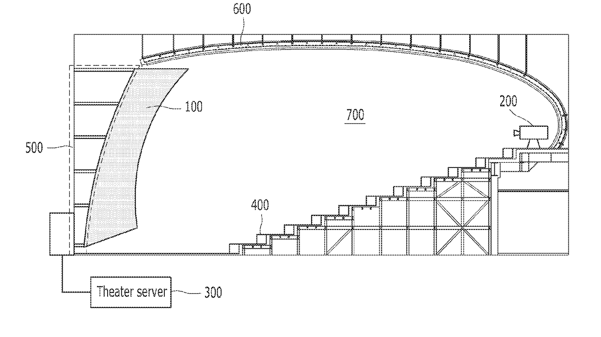
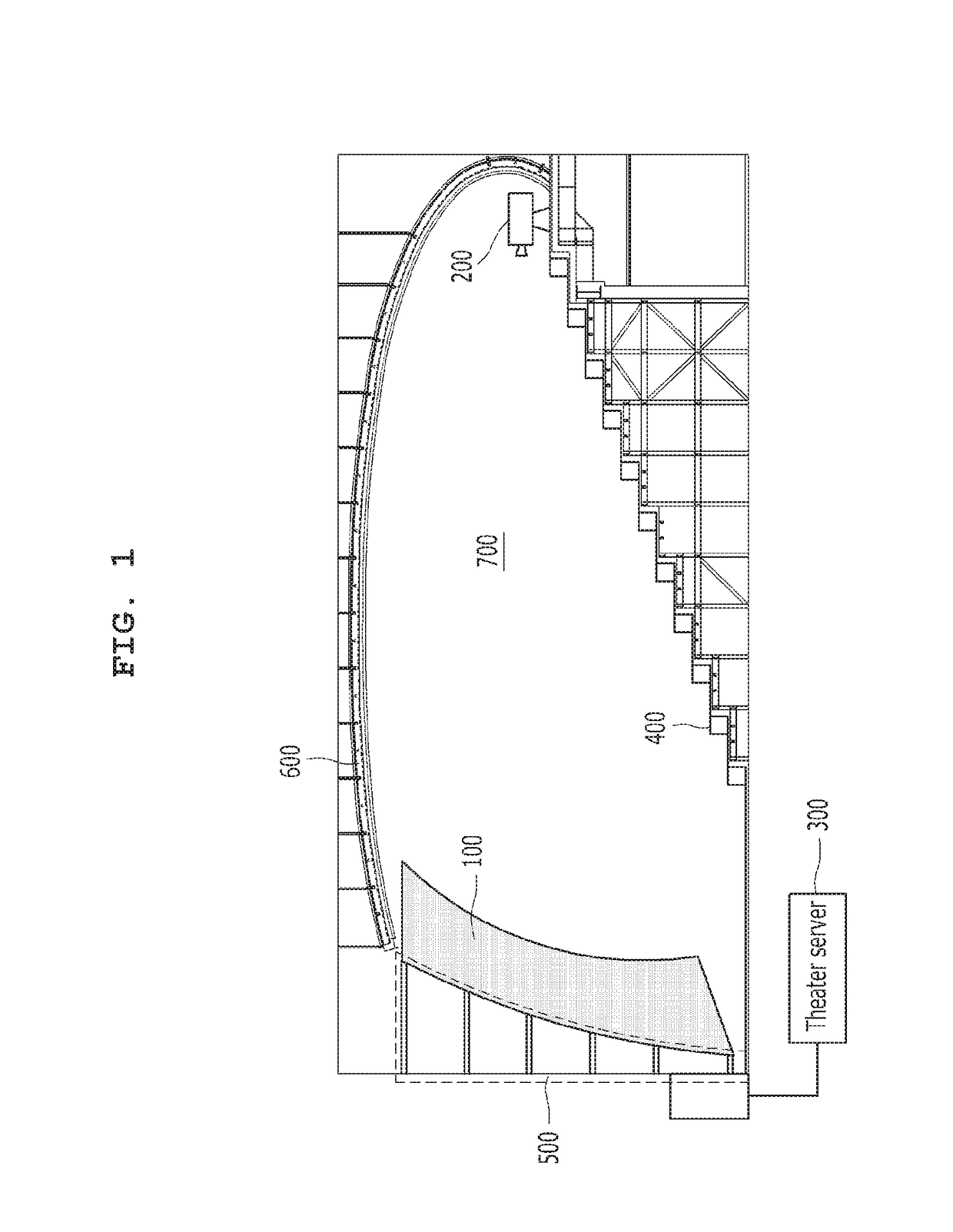
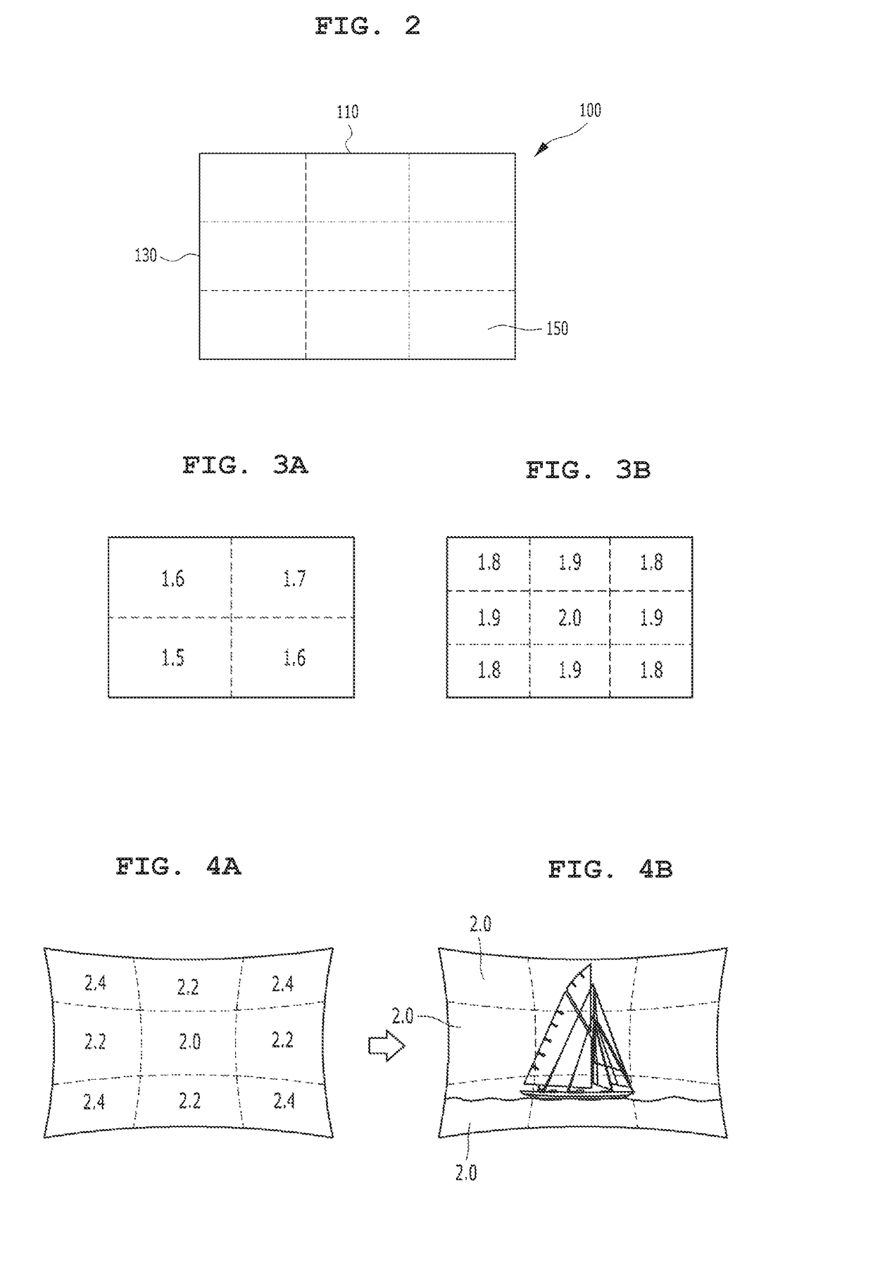
[0083]In accordance with the first embodiment, the method for fabricating the device 100 first starts from the step of setting two or more screen regions 150 on a single screen 100. That is, in a conventional technology, an attempt to separately set the screen regions 150 on the screen 100 has not been made. In contrast, an object of the present invention is to assign various screen reflectance values to respective regions on the screen 100. The first step starts from the setting a plurality of the screen regions 150 (S510).

[0084]Meanwhile, the plurality of screen regions 150 may be randomly set. In this case, it is preferred that the screen regions 150 are divided by taking into consideration a projection environment within a theater. For example, the screen regions 150 may be divided according to a projection environment within the theater, such as brightness for each scr...

second embodiment

[0090]FIG. 7 shows a method for fabricating the device 100 according to the present invention according to order.

[0091]The method for fabricating the screen 100 according to the second embodiment first starts from a step (S610) of projecting a content image on the screen 100. Step S610 is for taking into consideration a projection environment of the screen 100. Step S610 is for obtaining brightness of a content image (S620) in each of the screen regions of the screen 100 by projecting a content image, that is, a test image, on an uncompleted screen 100 having a generally uniform screen reflectance value in an environment similar to a projection environment in the future. Meanwhile, in this case, the image projected on the screen 100 may preferably include only a screen including only a single color. This is for more precisely measuring brightness values in the respective screen regions 150.

[0092]Meanwhile, a content image may be projected on the screen 100 by controlling different d...


PUM


Abstract

The present invention relates to a screen, and more specifically to a screen, to which a content images are projected, comprising screen regions each having a mutually different reflectance. According to the present invention, with respect to implementing a screen having a non-flat surface, as the content images can be projected onto all screen regions while maintaining uniform brightness, an audience can be provided with a content viewing environment by means of screens having a variety of shapes, while satisfactorily maintaining the quality of the of the projected a content images.

Description

TECHNICAL FIELD[0001]The present invention relates to a screen and, more particularly, to a screen including screen regions having different reflectance in the screen on which a content image is projected.[0002]According to the present invention, in implementing a screen other than a plane, a content image can be projected with uniform brightness in all of screen regions. Accordingly, there are advantages in that a content screening environment can be provided to audiences through screens of various shapes and quality of a projected content image can be excellently maintained.BACKGROUND ART[0003]In line with the recent diversification of movie content, a theater that is the space where the movie content can be watched is also greatly advanced. More specifically, many theaters consider various means in order to provide audiences with a higher three-dimensional (3-D) effect and a higher sense of immersion away from the frame of a screening environment in which a conventional 2-D image...

Claims


Application Information

Patent Timeline
Patent Type & Authority Applications(United States)
IPC IPC(8): G03B21/606G01J1/44B05D7/00G03B21/60B05D5/06H04N13/363
CPCG03B21/606G03B21/60G01J1/44B05D7/54B05D5/063G03B21/565E04H3/22G03B21/562G03B21/58G03B37/04G03B2206/00H04N13/363F16B2200/83E04B1/19F16B1/00F16B47/00F16M11/04F16M11/18F16M11/22E04C3/38G03B21/56A47C1/024A47C1/124A47C3/18A47C31/00E04H3/30E04B1/942E04B9/0407E04B9/0464E04B9/061E04B9/18H04N13/398G03B21/003H04N9/3147H04N9/3188
Inventor KOO, BON ILSONG, BYOUNG JUNKOH, HAE JEONGKIM, MIN JUNGKIMKIM, OK SUNPARK, NO CHANSEONG, IN JAECHOI, YOUNG WOOK
Owner CJ CGV
Why Eureka
Try Eureka