Unlock instant, AI-driven research and patent intelligence for your innovation.

Imaging apparatus, control method of imaging apparatus, and program

Inactive Publication Date: 2017-07-20
CANON KK
View PDF9 Cites 2 Cited by
  • Summary
  • Abstract
  • Description
  • Claims
  • Application Information

AI Technical Summary

Benefits of technology

This patent is about an imaging device that uses different methods to read its pixels. The goal is to reduce the impact of different types of noise that can occur with each method. The technical effect is to improve the accuracy and quality of the imaging device.

Problems solved by technology

This takes a lot of time to realize phase difference detection.
However, to read signals of one frame by the use of the imaging element disclosed in Japanese Patent Laid-Open No. 2013-068759, when separate readout and addition readout are selectively performed by line, there is an issue that the level of noise varies from line to line.
This decreases the operating frequency range between the signals and increases flicker noise.
Accordingly, when focus detection is conducted only in part of an image and signals for focus detection are read only from the rows in that part, there arises an issue that the noise level varies between the lines in which focus detection is conducted and the rows in which focus detection is not conducted.

Method used


Image

  • Imaging apparatus, control method of imaging apparatus, and program
  • Imaging apparatus, control method of imaging apparatus, and program
  • Imaging apparatus, control method of imaging apparatus, and program

Examples


first embodiment

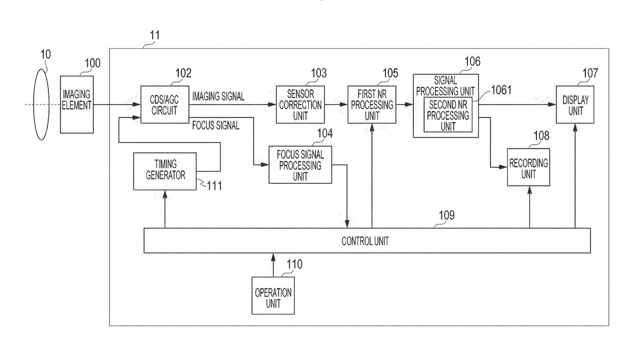
[0020]FIG. 1 is a block diagram illustrating a schematic configuration of an imaging apparatus of the embodiment including an image processing device 11 that processes signals output from an imaging element 100.

[0021]In the configuration of FIG. 1, light flux entered via a lens unit 10 forms an image on a light receiving surface of the imaging element 100. An object image formed on the light receiving surface is subjected to photoelectric conversion into electric charges according to the amount of incident light at two PDs 21a and 21b of a pixel 20 of the imaging element 100 illustrated in FIG. 2A, and the electric charges are accumulated there. The electric charges accumulated in the PDs 21a and 21b are sequentially read as voltage signals according to the electric charges from the imaging element 100 based on a driving pulse provided by a timing generator 111 under an instruction from a control unit 109 composed of a CPU. The control unit 109 instructs the timing generator 111 to ...

second embodiment

[0090]In a second embodiment, the process by the second NR processing unit 1061 is different from that in the first embodiment. The other conditions, the method of PD readout, the configuration of the image processing apparatus, the process at the time of frame readout, and the process by the first NR processing unit 105 are the same as those in the first embodiment and thus descriptions thereof will be omitted.

[0091]FIG. 10 is a schematic block diagram of the second NR processing unit 1061 according to the second embodiment.

[0092]The second NR processing unit 1061 first saves an image signal output from the first NR processing unit 105 in a memory 1003.

[0093]Further, a low pass filter (LPF) processing unit 1011 performs an LPF process on the image signal output from the first NR processing unit 105, and a reduction processing unit 1012 performs a reduction process of the size of the image signal and saves the reduced image signal in a memory 1013.

[0094]Moreover, an LPF processing u...

third embodiment

[0108]In a third embodiment, the control unit 109 can switch between the mode of switching the readout operation by line and the mode of performing the division readout on all the pixels in the effective region 301a of the pixel section 301 explained above in relation to the first and second embodiments. The processing speed can be higher in the case of performing the division readout only in part of the region than in the case of performing the division readout in the entire region. On the contrary, in the case of performing the division readout in the entire region, it is possible to obtain the focus detection signals from the entire region and perform effectively image processing (for example, blurring performance) taking range information into account. Accordingly, it can be conceived that the division readout is performed in part of the region in a moving image capturing mode or a high-speed continuous shooting mode in which a higher processing speed is required, and the divisi...


PUM


Abstract

An imaging apparatus includes an imaging element, a readout unit, and a signal processing unit. The imaging element includes pixels that have photoelectric conversion units for one micro lens. The readout unit performs a first readout operation on pixels included in a first region of the imaging element to read signals according to accumulated electric charges, and performs a second readout operation on pixels included in a second region different from the first region to read signals according to accumulated electric charges. The signal processing unit makes a correction for reducing noise levels to the signals readout by the readout unit. The signal processing unit makes the correction to the signals acquired from the first region such that differences between noise levels included in the signals read by the first readout operation and the second readout operation become smaller after the correction by the signal processing unit.

Description

BACKGROUND OF THE INVENTIONField of the Invention[0001]An embodiment relates to a technique for reducing noise in an image signal generated by an imaging apparatus.Description of the Related Art[0002]Japanese Patent Laid-Open No. 2013-068759 proposes an imaging element in which pixels having two photoelectric conversion units for one micro lens are laid out on the entire surface. To detect a phase difference, it is necessary to perform a readout operation on the pixels with the plurality of photoelectric conversion units in such a manner as to obtain at least two signals with a parallax. To this end, there is a possible method by which to output a signal obtained by one of the photoelectric conversion units and then output a signal obtained by the other photoelectric conversion unit, for example. Alternatively, there is another possible method by which to first output a signal obtained by one photoelectric conversion unit and then add up signals obtained by two photoelectric convers...

Claims


Application Information

Patent Timeline
IPC IPC(8): H04N5/357H04N5/378
CPCH04N5/3572H04N5/3575H04N5/378H01L27/14627H04N25/60H04N25/616H04N25/778G06T5/70H04N25/75
Inventor OOTA, MAKOTO
Owner CANON KK