Lamiinate-type power storage element and manufacturing method thereof

Active Publication Date: 2017-07-27
FDK CORP
View PDF1 Cites 1 Cited by
  • Summary
  • Abstract
  • Description
  • Claims
  • Application Information

AI Technical Summary

Benefits of technology

[0029]According to the laminate-type power storage element of the present disclosure, the electrode body can be kept from being damaged during implementation to the circuit board using thermocompression bonding technology and thus a short circuit can be certainly kept from being g

Problems solved by technology

However, solder thickness control during soldering is difficult.
When the laminate-type power storage element is used in for example, the above card electronic device, the solder may become thick at the implementation region so that the laminate-type power storage element may not be able to be incorporated into the card electronic device.
However, since ultrasonic welding is associated with ultrasonic vibration caused by a large amount of energy creating frictional heat that melts the contact surface between the electrode terminal plates and the print wiring, the electrode terminal plates may be damaged or disconnected, depending on circumstances, in cases where th

Method used


Image

  • Lamiinate-type power storage element and manufacturing method thereof
  • Lamiinate-type power storage element and manufacturing method thereof
  • Lamiinate-type power storage element and manufacturing method thereof

Examples


Example

Working Examples

Structure

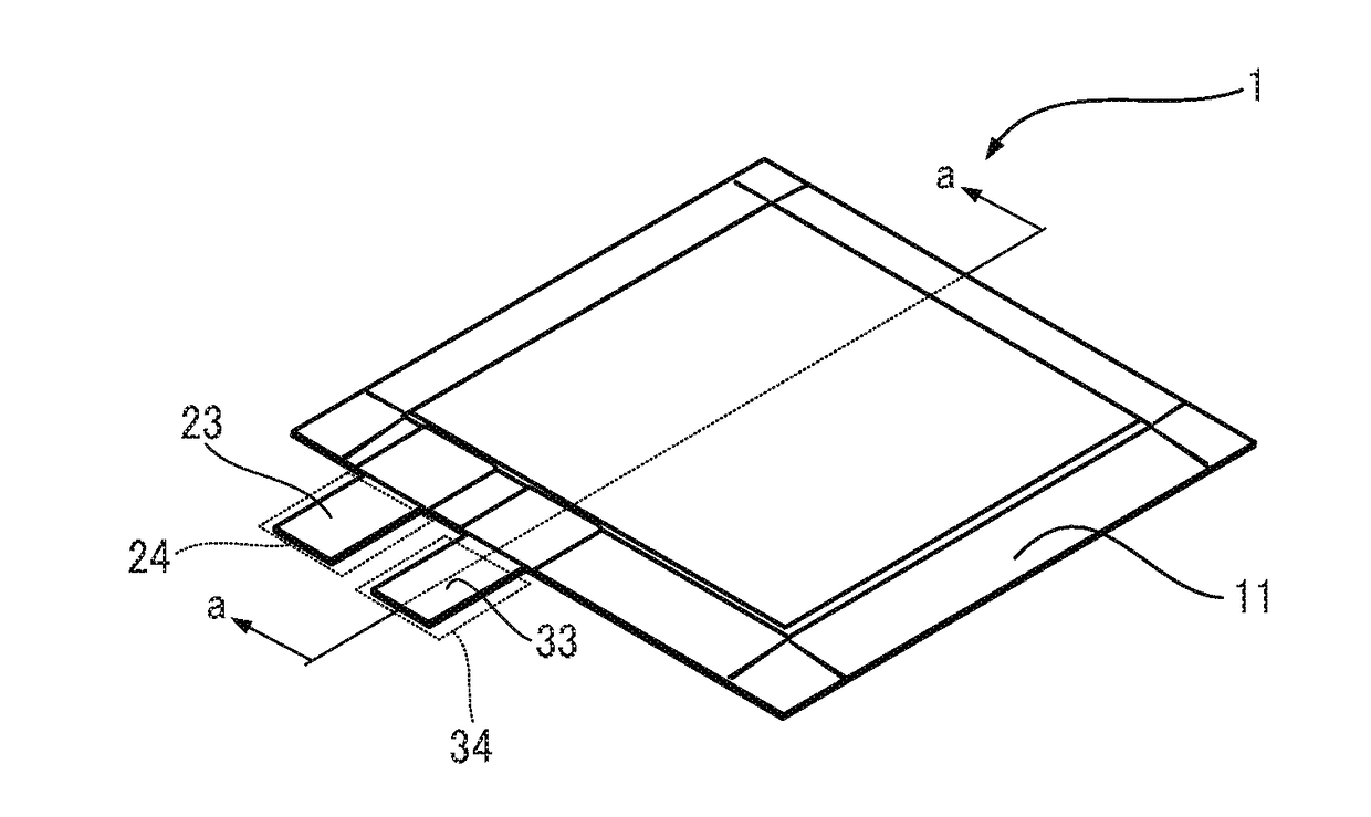
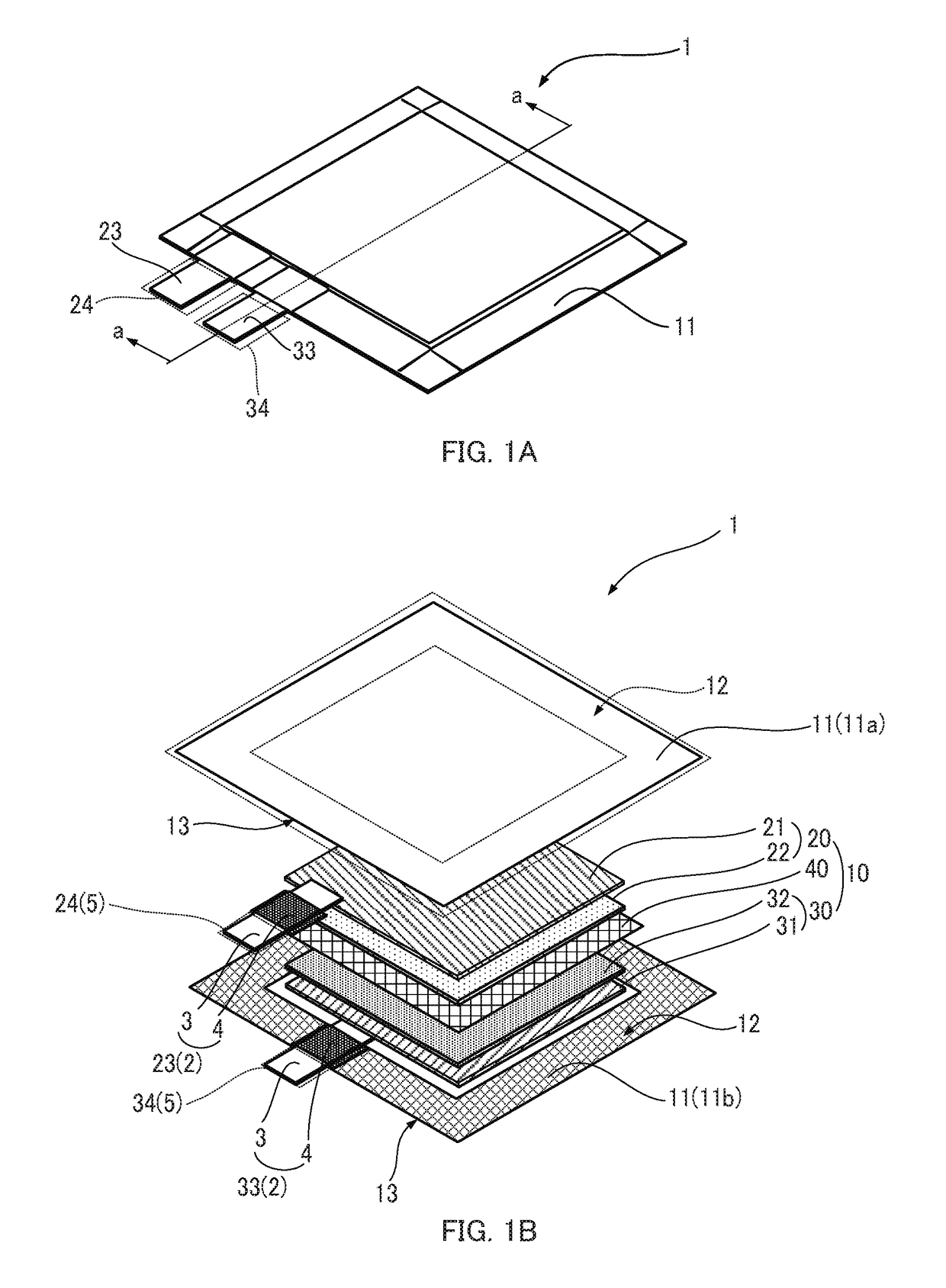
[0051]The laminate-type power storage element (hereinafter referred as power storage element) according to a working example of the present invention has a special configuration that serves in place of a support tab and is made to keep the electrode body from being damaged by a thermocompression bonding process as well as a short-circuit from being generated between the electrode terminals with this unique configuration. The inner structure of the power storage element according to the working example is similar to that of the power storage element 1 illustrated in FIG. 1B.

[0052]FIGS. 5A, 5B, 6A and 6B illustrate a laminate-type power storage element (hereinafter also referred to as a power storage element 1a) according to the working example of the present invention. The following has each of the up-down, front-rear and right-left directions defined similar to FIGS. 3A to 3C. FIG. 5A is an external view of the power storage element 1a when seen from above a...


PUM


Abstract

A laminate-type power storage element, including an exterior body that is formed in a flat bag shape, and an electrode body that has a sheet-shaped positive electrode and a sheet-shaped negative electrode layered via a separator and that is sealed inside the exterior body together with an electrolytic solution, wherein electrode terminal plates of the positive electrode and the negative electrode are guided in an identical direction from a predetermined margin of the exterior body to an outside of the exterior body, and a support part that is made with a film shaped resin having insulating and heat-resistant properties is formed on principal surface sides of the electrode terminal plates at a region that is along the predetermined margin and covers up to tip ends of the electrode terminal plates.

Description

CROSS-REFERENCE TO RELATED APPLICATIONS[0001]The present application claims priority from Japanese Patent Application No. 2016-12988 filed on Jan. 27, 2016, which is herein incorporated by reference.BACKGROUND[0002]Technical Field[0003]Embodiments of this disclosure generally relate to a laminate-type power storage element that houses a power generating element in an exterior body formed of laminated films and a manufacturing method of the power storage element.[0004]Related Art[0005]As a form of a power storage element such as a primary battery, a secondary battery, and an electric double layer capacitor, there has been provided a laminate-type power storage element that seals a flat plate-shaped electrode body together with electrolytic solution in a flat-bag-shaped exterior body formed of laminated films. Since the laminate-type power storage element easily achieves both a large capacity and downsizing and thinning and is also excellent in heat radiation performance, the laminate...

Claims


Application Information

Patent Timeline
IPC IPC(8): H01M2/32H01M6/02H01M2/30H01M2/02H01M50/571H01M50/119H01M50/121H01M50/124H01M50/178H01M50/55H01M50/553
CPCH01M2/32H01M2/021H01M2220/30H01M2/30H01M6/02H01M10/0436Y02E60/10H01M50/24H01M50/121H01M50/124H01M50/178H01M50/55H01M50/553H01M50/119H01M50/571
Inventor MANO, TSUKASAHIRATA, DAISUKENISHIMURA, NAOAKIIIDA, YUYAITO, RYUJI
Owner FDK CORP
Why Eureka
Try Eureka