Apparatus for Testing an Object

a technology for objects and apparatus, applied in the field of apparatus for testing objects, can solve the problems of low testing efficiency, achieve the effects of improving testing efficiency, simple configuration, and easy and fast testing of objects

Active Publication Date: 2017-07-27
ISMEDIA
View PDF1 Cites 2 Cited by
  • Summary
  • Abstract
  • Description
  • Claims
  • Application Information

AI Technical Summary

Benefits of technology

[0032]According to the present disclosure, there is provided an apparatus for testing an object, capable of testing an object easily and quickly from a position that an operator wants.
[0033]Further, the object may be tested from various positions, thereby significantly improving the testing efficiency.
[0034]Further, due to its simple configuration, the apparatus for testing an object may be easily manufactured and maintained at reduced cost.

Problems solved by technology

This leads to a problem of low testing efficiency, since in reality, users take photos or videos from various positions, for example, by holding the camera almost vertically or laying the camera towards the ground, whereas testing a camera module is not conducted from various positions.
Thus, sometimes a camera module test is conducted from various positions using a semi-circular chart having the shape of a dome, which is also a problem since it is difficult to use this type of semi-circular chart due to its high manufacturing and maintenance cost.

Method used


Image

  • Apparatus for Testing an Object
  • Apparatus for Testing an Object
  • Apparatus for Testing an Object

Examples


first embodiment

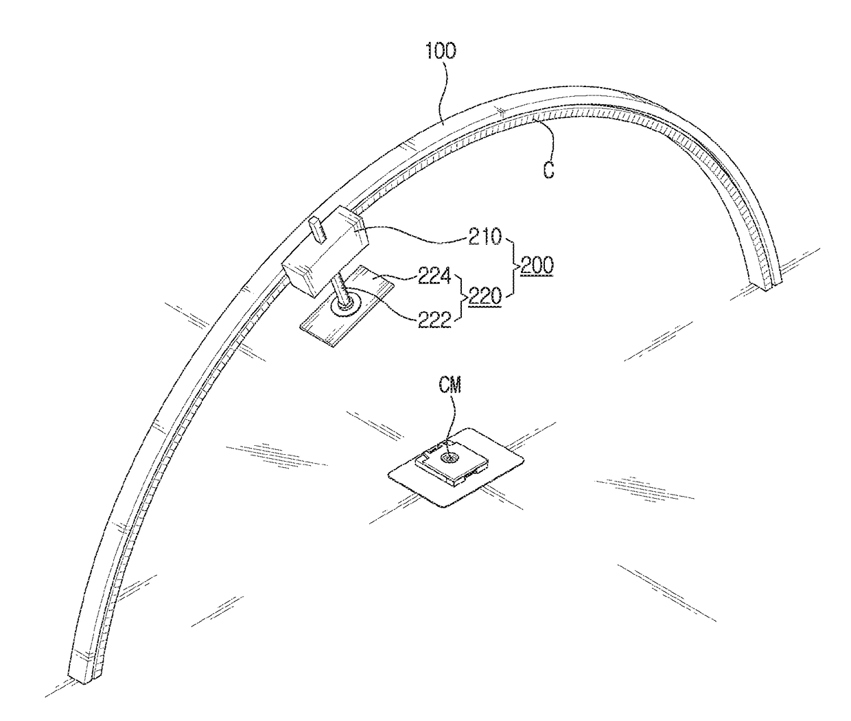
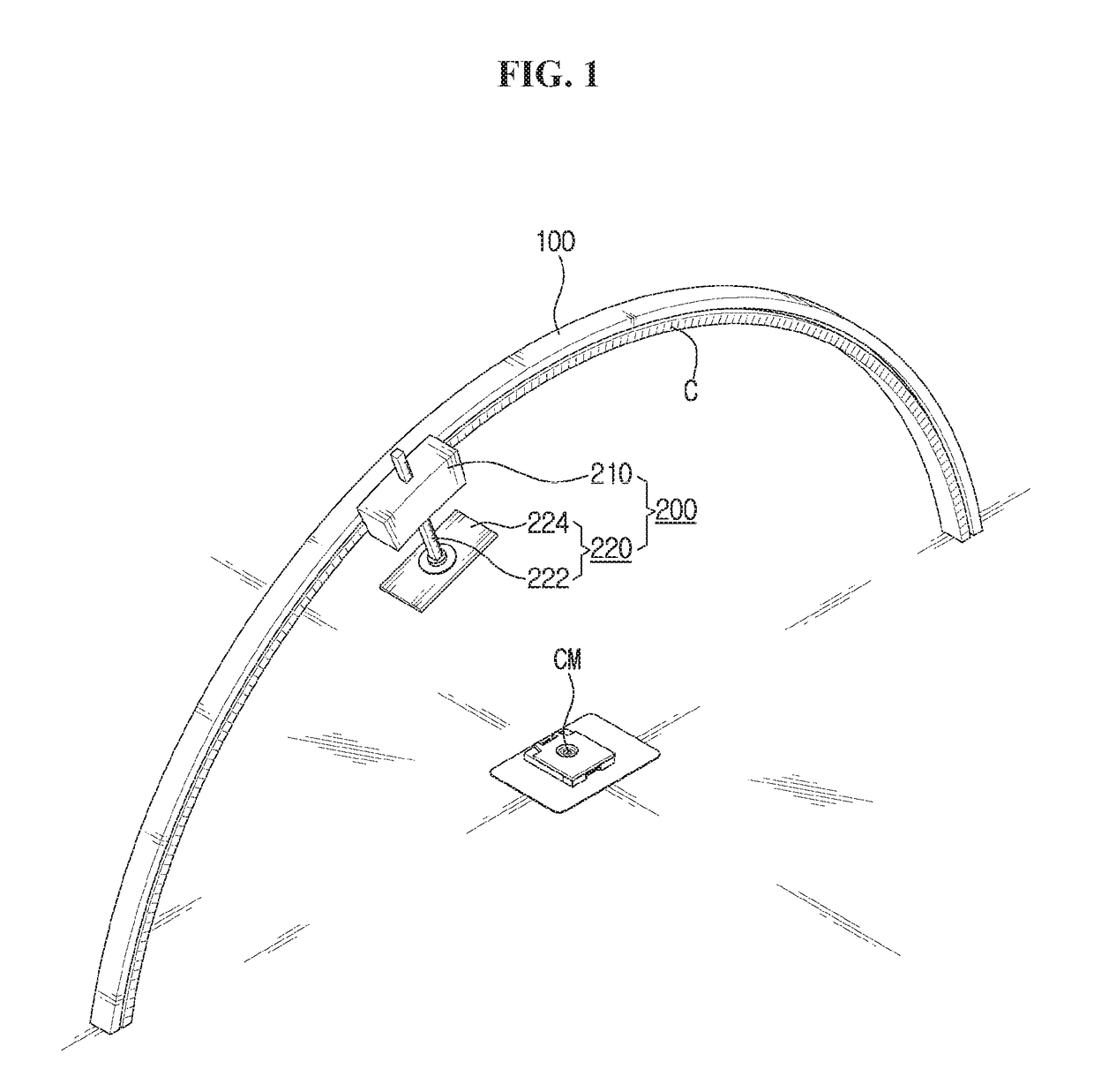
[0041]FIG. 1 is a schematic view schematically illustrating an apparatus for testing an object according to the present disclosure.

[0042]Referring to FIG. 1, the apparatus for testing an object according to the first embodiment of the present disclosure is configured to include largely a guide means 100 and a testing means 200.

[0043]The guide means 100 is a member that forms an arc shape whose center is an object CM. In particular, the guide means 100 is formed along a circumference of a virtually-drawn circle, wherein the object CM is positioned at a center of the virtual circle.

[0044]Such a guide means 100 is a frame having the shape of a bent stick, a bent pipe or a bent bar. Here, in FIG. 1, the guide means 100 is illustrated as having a semi-circular shape, but depending on the type or size of the object CM, or depending on the type of the test to be conducted by the testing means 200 that will be explained hereinafter, the shape of the guide means may form a shape where the le...

third embodiment

[0061]FIG. 3 and FIG. 4 are enlarged views of some parts of the apparatus for testing an object according to a second and the present disclosure.

second embodiment

[0062]First of all, FIG. 3A is an enlarged view of the apparatus for testing an object and FIG. 3B is a cross-sectional view of FIG. 3A.

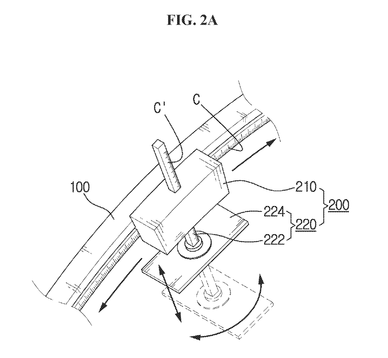
[0063]Such an apparatus for testing an object according to the second embodiment of the present disclosure is configured to be similar as that of the aforementioned first embodiment, except that the shape of the guide means 100 and the position of the moving unit 210 mounted onto the guide means 100 to move are different from those in the first embodiment.

[0064]That is, in the second embodiment, the guide means 100 consists of two frames having an identical semi-circular shape, and the two frames are connected by a plurality of cross-arms.

[0065]The moving unit 210 is mounted onto an upper surface of the guide means 100, so that it may move along the guide means 100. The guide unit 222 is installed to penetrate the moving unit 210 and the guide means 100, and moves between two cross-arms. Further, the chart unit 224 coupled to the guide unit 222 app...


PUM


Abstract

The present disclosure relates to an apparatus for testing an object, the apparatus including a guide means and a testing means, and capable of easily and quickly testing an object from a position where an operator wants, and of testing an object from various positions, thereby significantly improving the testing efficiency, and also having a simple configuration so that it is easy to manufacture and maintain at reduced cost.

Description

CROSS-REFERENCE TO RELATED APPLICATION[0001]This application claims priority under 35 U.S.C. §119 to Korean Patent Application No.10-2016-0009474, filed Jan. 26, 2016, which is herein incorporated by reference in its entirety.BACKGROUND[0002]Field[0003]The present disclosure relates to an apparatus for testing an object, and more particularly, to an apparatus for testing an object, that is capable of testing an object easily and quickly from a position that an operator wants, and of testing an object from various positions, thereby significantly improving the testing efficiency, and also having a simple configuration so that it is easy to manufacture and maintain at reduced cost.[0004]Description of Related Art[0005]The latest mobile equipment such as smart phones and tablet PCs are generally equipped with camera modules, and using such mobile electronic equipment that uses camera modules, photos or videos can be photographed.[0006]A conventional camera module does not have a large ...

Claims


Application Information

Patent Timeline
Patent Type & Authority Applications(United States)
IPC IPC(8): H04N17/00H04N5/225
CPCH04N5/2256H04N17/002G03B43/00G03B17/561H04N23/56
Inventor HONG, SEONG CHEOLLEE, JONG DAE
Owner ISMEDIA
Why Eureka
Try Eureka