Cleaning apparatus with combing unit for removing debris from cleaning roller

Active Publication Date: 2017-08-03
SHARKNINJA OPERATING LLC
View PDF10 Cites 35 Cited by
  • Summary
  • Abstract
  • Description
  • Claims
  • Application Information

AI Technical Summary

Problems solved by technology

One of the challenges with vacuum cleaner design is to control engagement of the suction conduit with a surface being cleaned to provide the desired amount of suction.
If the suction conduit is directly engaged with the surface and thus sealed on all sides, air will stop flowing into the suction conduit and the suction motor may be damaged as a result.
If the agitator in the suction conduit is unable to loosen the debris or

Method used


Image

  • Cleaning apparatus with combing unit for removing debris from cleaning roller
  • Cleaning apparatus with combing unit for removing debris from cleaning roller
  • Cleaning apparatus with combing unit for removing debris from cleaning roller

Examples


Embodiment Construction

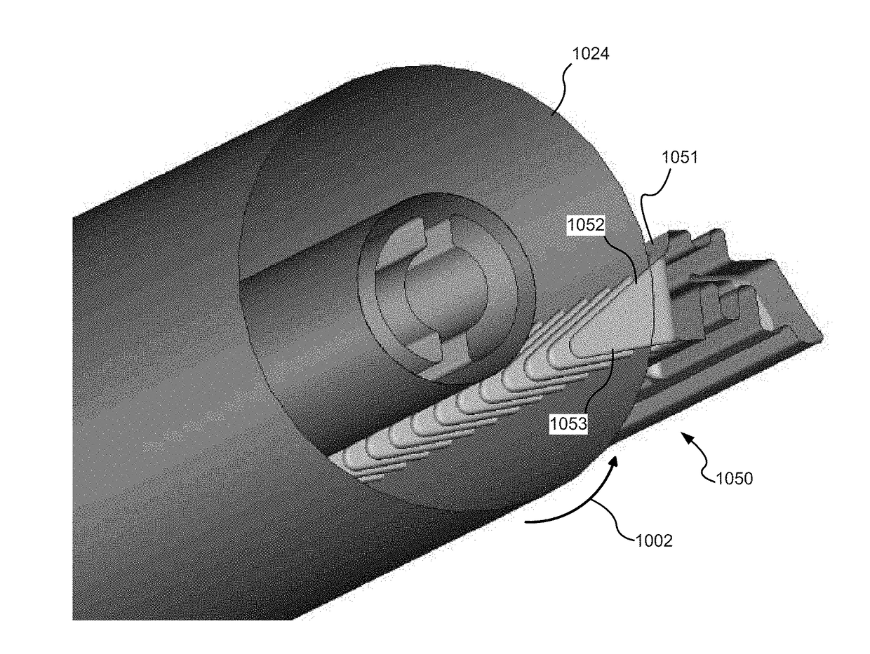
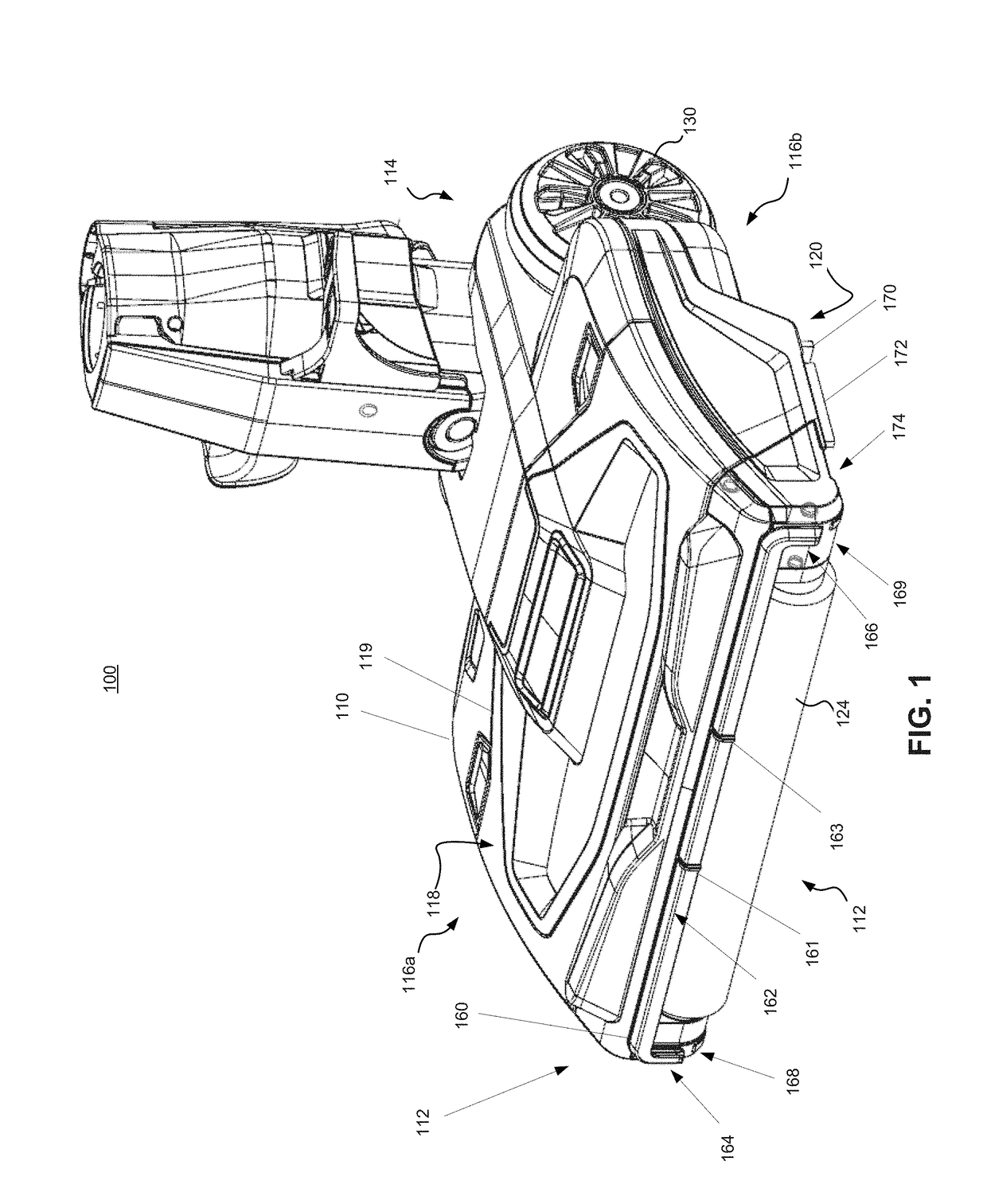
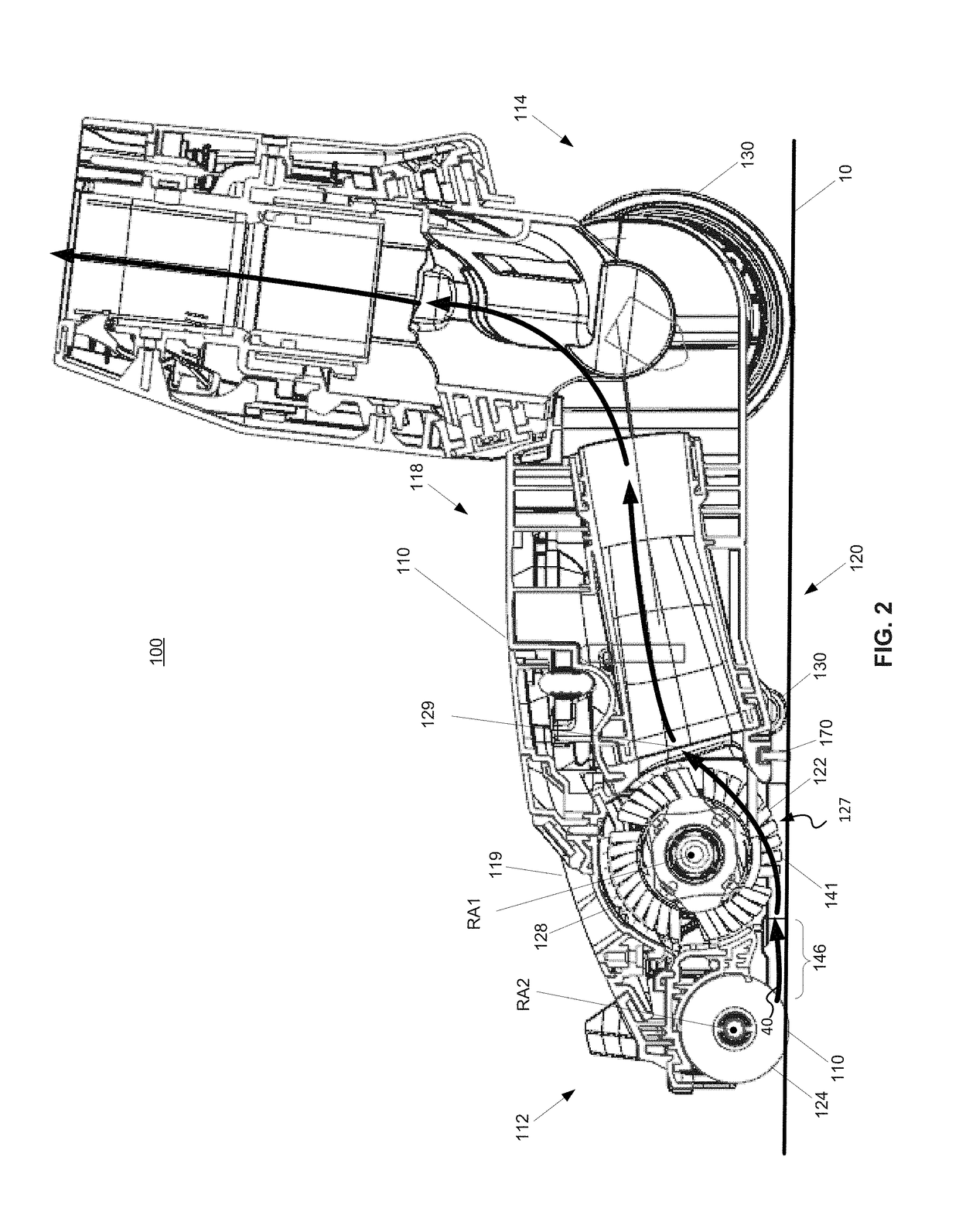
[0028]A cleaning apparatus, consistent with embodiments of the present disclosure, includes a combing unit (also referred to as a debriding unit or rib) including a series of spaced protrusions or teeth extending into a cleaning roller for preventing build up and removing debris (such as hair, string, and the like). The protrusions extend along a substantial portion of the cleaning roller and extend partially into the cleaning roller to intercept the debris as it passes around the roller. The protrusions have angled leading edges that are not aligned with a rotation center of the cleaning roller and are directed into or against a direction of rotation of the cleaning roller. The combing unit and protrusions have a shape and configuration designed to facilitate debris removal from the cleaning roller with minimal impact on the operation of the cleaning apparatus. The cleaning apparatus may include a surface cleaning head of an upright vacuum cleaner or sweeper or a robotic vacuum cle...


PUM


Abstract

A cleaning apparatus includes a combing unit including a series of spaced protrusions or teeth extending into a cleaning roller for preventing build up and removing debris (such as hair, string, and the like). The protrusions extend along a substantial portion of the cleaning roller and extend partially into the cleaning roller to intercept the debris as it passes around the roller. The protrusions have angled leading edges that are not aligned with a rotation center of the cleaning roller and are directed into or against a direction of rotation of the cleaning roller. The combing unit and protrusions have a shape and configuration designed to facilitate debris removal from the cleaning roller with minimal impact on the operation of the cleaning apparatus. The cleaning apparatus may include a surface cleaning head of an upright vacuum cleaner or sweeper or a robotic vacuum cleaner.

Description

CROSS-REFERENCE TO RELATED APPLICATIONS[0001]The present application claims the benefit of U.S. Provisional Application No. 62 / 469,853, filed Mar. 10, 2017 and is a continuation-in-part of U.S. patent application Ser. No. 15 / 331,045, filed Oct. 21, 2016, which claims the benefit of U.S. Provisional Patent Application Ser. No. 62 / 244,331 filed Oct. 21, 2015, U.S. Provisional Patent Application Ser. No. 62 / 248,813 filed Oct. 30, 2015, and U.S. Provisional Patent Application Ser. No. 62 / 313,394 filed Mar. 25, 2016, all of which are fully incorporated herein by reference. The present application is also a continuation-in-part of International Application No. PCT / US2016 / 058148, filed on Oct. 21, 2016, which is fully incorporated herein by reference.TECHNICAL FIELD[0002]The present disclosure relates to cleaners with cleaning rollers and more particularly, to a cleaning apparatus, such as a surface cleaning head for a vacuum cleaner, with a combing unit for removing debris from a cleaning...

Claims


Application Information

Patent Timeline
IPC IPC(8): A47L9/06A47L5/30A47L9/04A47L5/26
CPCA47L9/0613A47L5/26A47L9/0488A47L9/0477A47L5/30A47L9/30
Inventor THORNE, JASON B.MING, YAODER MARDEROSIAN, DANIEL R.MEYER, DANIELCLEARY, PATRICKHOWE, GORDONWUGAO WENXIU, NANCY
Owner SHARKNINJA OPERATING LLC
Why Eureka
Try Eureka