Mounting Structure

a technology of mounting structure and mounting plate, which is applied in the direction of machine support, electric propulsion mounting, vehicle sub-unit features, etc., can solve the problems of transaxle case being subject to failure, reducing fixing strength, etc., and achieves the effect of carrying out easily and quickly

Active Publication Date: 2017-08-03
TOYOTA JIDOSHA KK
View PDF0 Cites 3 Cited by
  • Summary
  • Abstract
  • Description
  • Claims
  • Application Information

AI Technical Summary

Benefits of technology

[0012]In the mounting structure described above, although the rear-side support bracket of the electronic control unit is fixed to the protruding portion, protruding from the transaxle case toward the rear side of the vehicle, of the intermediate bracket, since the engaging projection is provided to at least one of the upper surface of the intermediate bracket or the bottom surface of the electronic control unit in the region where the intermediate bracket is in surface contact with the mounting surface of the transaxle case, the engaging projection protruding in the direction toward the upper surface of the intermediate bracket and the bottom surface of the electronic control unit, when the electronic control unit approaches the transaxle case at the time of vehicle collision, the intermediate bracket is pressed against the mounting surface of the transaxle case via the engaging projection. Accordingly, even when a moment is generated by a load that is applied from the rear-side support bracket to the protruding portion of the intermediate bracket, resulting in that a lifting load acts on a fixed portion of the intermediate bracket to the transaxle case, that is cancelled due to a pressing load by the engaging projection, so that the fixing strength of the intermediate bracket is properly ensured. Further, since it is sufficient to only provide the engaging projection, a complicated design change is not necessarily required, and a design change can be easily carried out without impairing the assembling workability.
[0014]According to the mounting structure described above, since the engaging projection is provided at the positions under the pair of side walls located on both sides of the electronic control unit in the width direction of the vehicle, the intermediate bracket is firmly pressed against the mounting surface of the transaxle case via the highly rigid side walls, and damage to the electronic control unit due to a reaction force of the pressing load is suppressed. In addition, since the engaging projection is provided at the positions under the pair of side walls on both sides in the width direction of the vehicle, the intermediate bracket is pressed against the mounting surface relatively stably regardless of a collision manner, so that the fixing strength to the transaxle case is ensured more properly.
[0016]According to the mounting structure described above, the gap is provided between the intermediate bracket and the electronic control unit even at the portion where the engaging projection is provided, while both are brought into abutment with each other via the engaging projection at the time of vehicle collision. Therefore, the attaching work for attaching the electronic control unit to the transaxle case using the support brackets can be carried out easily and quickly, and the required accuracy of dimensions of the respective portions can be relaxed compared to a case where the engaging projection is provided such that the intermediate bracket and the electronic control unit are substantially in contact with each other.

Problems solved by technology

However, in the case where the rear-side support bracket is fixed at the position spaced from the transaxle case toward the rear side of the vehicle as described above, when a collision load toward the rear side of the vehicle is applied to the electronic control unit at the time of vehicle collision, a moment is generated by a load that is applied from the rear-side support bracket to the intermediate bracket, so that there is a possibility that a load in a lifting direction may act on a fixed portion of the intermediate bracket to the transaxle case, resulting in a decrease in fixing strength.
When the fixing strength is decreased, the intermediate bracket along with the electronic control unit may come off the transaxle case, or the transaxle case may be subjected to failure due to the dislocation of the intermediate bracket.
Further, since it is sufficient to only provide the engaging projection, a complicated design change is not necessarily required, and a design change can be easily carried out without impairing the assembling workability.

Method used


Image

  • Mounting Structure
  • Mounting Structure
  • Mounting Structure

Examples


Embodiment Construction

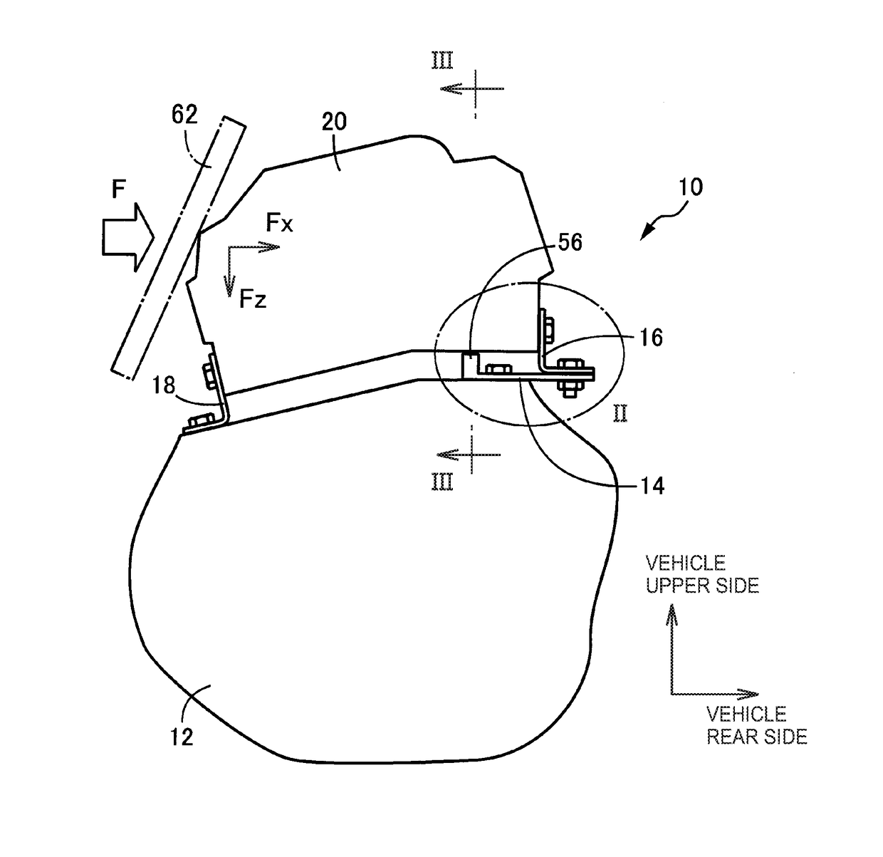
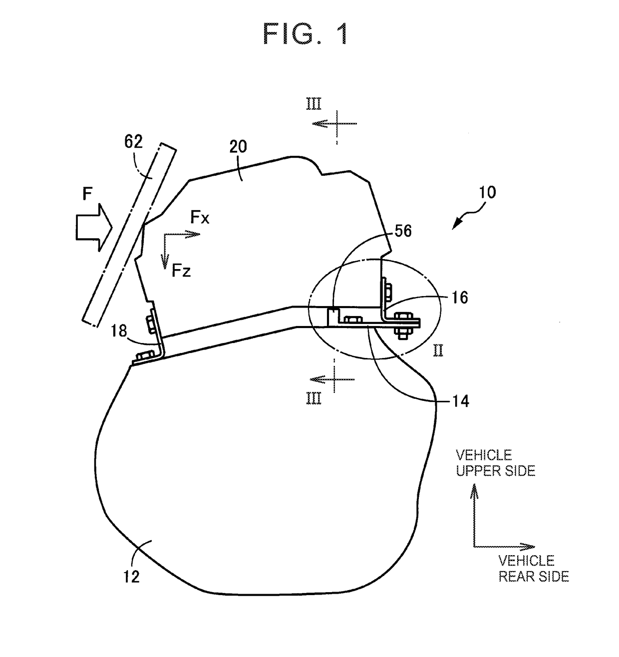
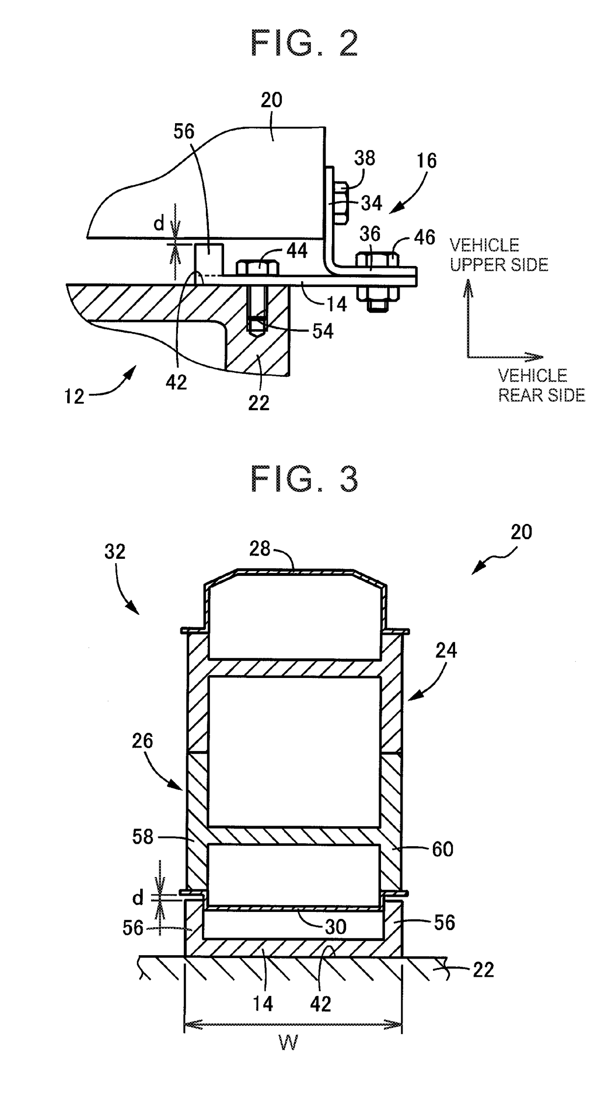
[0028]A transaxle case houses therein a transaxle. The transaxle is a power transmission device that is transversely mounted in an FF (front-engine front-drive) vehicle. The transaxle includes a transmission and a final reduction gear and is housed in the transaxle case that is commonly used. The transmission may be a stepped or continuously variable mechanical transmission of a planetary gear type, a belt type, or the like, or may be an electric continuously variable transmission having an electric generator such as a motor generator and a differential mechanism. In the case of an electric vehicle such as a hybrid vehicle, a vehicle-travel electric motor such as a motor generator can also be housed in the transaxle case. An electronic control unit is configured by including, for example, inverters and control circuits for controlling the above-described electric generator and electric motor, but may alternatively be provided with a control device for performing shift control of the...


PUM


Abstract

Provided is a mounting structure including an electronic control unit, a plurality of support brackets, a transaxle case, an intermediate bracket protruding from the transaxle case toward a rear side of the vehicle, and an engaging projection. The engaging projection is a projection that is provided to at least one of an upper surface of the intermediate bracket or a bottom surface of the electronic control unit in a region where the intermediate bracket is in surface contact with a mounting surface of the transaxle case, the engaging projection protruding in a direction toward the upper surface of the intermediate bracket and the bottom surface of the electronic control unit. The engaging projection presses the intermediate bracket against the mounting surface of the transaxle case responding to displacement of the electronic control unit at the time of vehicle collision.

Description

CROSS-REFERENCE TO RELATED APPLICATIONS[0001]This application claims priority to Japanese Patent Application No. 2016-016709 filed on Jan. 29, 2016, the entire contents of which are hereby incorporated by reference.BACKGROUND[0002]1. Technical Field[0003]The present disclosure relates to a technique of disposing an electronic control unit above a transaxle via a plurality of support brackets.[0004]2. Description of Related Art[0005]There is known a mounting structure in which (i) an electronic control unit has a plurality of support brackets that are provided so as to be spaced apart from each other in a longitudinal direction of a vehicle and to protrude downward, and (ii) the electronic control unit is attached to a transaxle case in a state of floating above the transaxle case via the plurality of support brackets. The structure described in Japanese Patent Application Publication No. 2014-168356 (JP 2014-168356 A) is its one example in which a power control unit (PCU) including ...

Claims


Application Information

Patent Timeline
Patent Type & Authority Applications(United States)
IPC IPC(8): B60K26/00B60K20/00B60K17/16B60K6/405B60K6/26B60K6/36
CPCB60K26/00B60K6/26B60K20/00B60K17/16B60K6/405B60K6/36B60K1/00B60K17/08B60Y2306/01B60Y2410/10
Inventor IKEDA, AKIHIKOYAMASHITA, TEPPEISHIGEMATSU, FUMIAKI
Owner TOYOTA JIDOSHA KK
Why Eureka
Try Eureka