
Stack frame

a technology of mounting holes and brackets, applied in the field of brackets, can solve the problems of difficult to ensure the fixing strength of the battery stack, difficult to provide the plurality of mounting holes to only one of the molded products, and large vibration, so as to reduce the force applied to the mounting holes, ensure the fixing strength, and ensure the fixing strength

Active Publication Date: 2020-06-11
TOYOTA JIDOSHA KK
View PDF0 Cites 0 Cited by
  • Summary
  • Abstract
  • Description
  • Claims
  • Application Information

AI Technical Summary

Benefits of technology

The present disclosure provides a stack frame that can securely hold a battery stack while meeting shape and dimension restrictions. The end frame member is joined to the cross member, and more mounting holes are provided in the end surface covered region to allow for easy transmission of vibration caused by the battery stack. This reduces force applied to the mounting holes, ensuring fixing strength of the battery stack. Overall, the disclosure ensures fixing strength while optimizing the shape and dimension of the battery stack.

Problems solved by technology

It is difficult to provide the plurality of mounting holes to only one of the molded products, and the plurality of mounting holes are often provided to the plurality of molded products.
Hence, when a vehicle equipped with a stack frame mounted with a battery stack travels on a rough road, great vibration is generated.
Due to occurrence of the vibration, there may be a possibility that the mounting holes receive force, which makes it difficult to ensure fixing strength for fixing the battery stack.
However, the shape and dimension of the stack frame have certain restrictions depending on the space in the vehicle and the peripheral equipment around the stack frame.
Hence, vibration caused by the battery stack can be easily transmitted to the cross member via the mounting holes.

Method used


Image

  • Stack frame
  • Stack frame
  • Stack frame

Examples


first embodiment

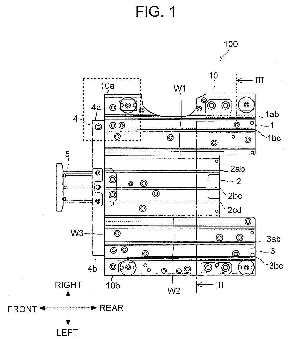
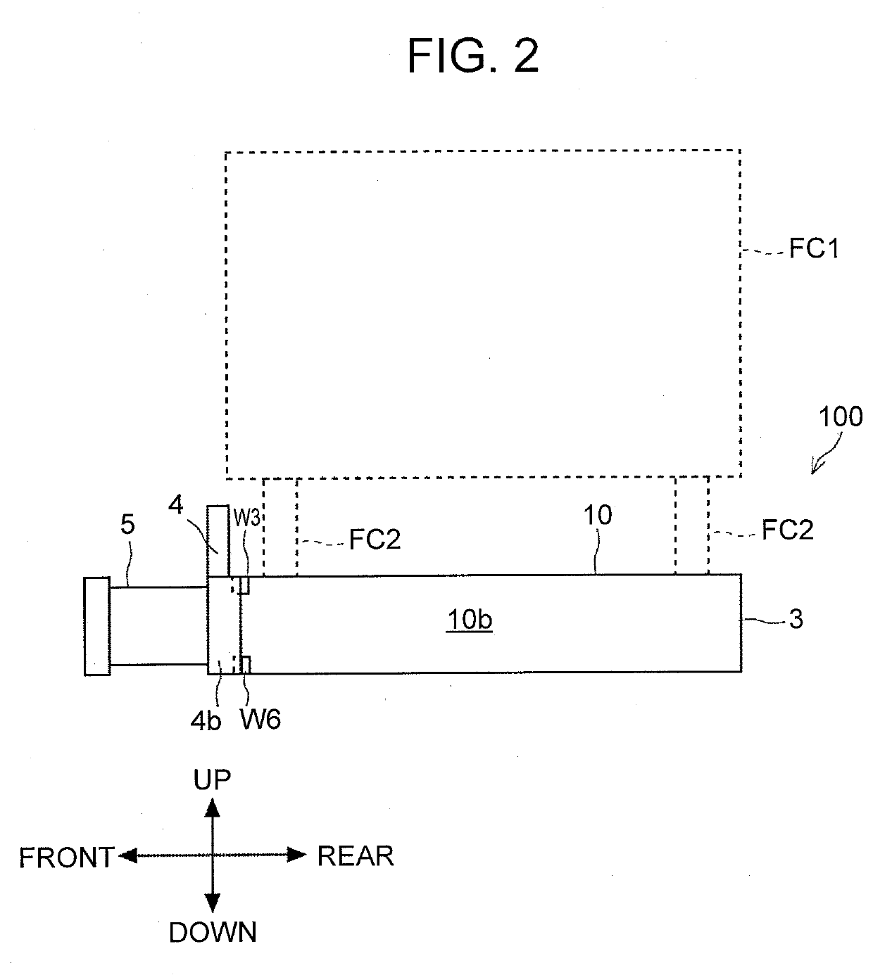
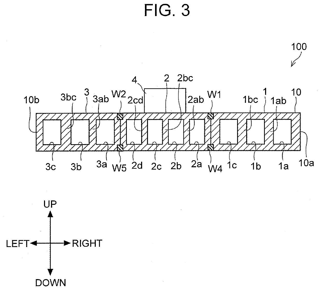
[0024]A stack frame according to the first embodiment will be described with reference to FIG. 1 to FIG. 4. FIG. 1 is a top view of the stack frame according to the first embodiment. FIG. 2 is a left side view showing the stack frame according to the first embodiment. FIG. 3 is a sectional view showing the stack frame according to the first embodiment. FIG. 4 is an enlarged view of an upper surface of the stack frame according to the first embodiment.

[0025]As a matter of course, three-dimensional orthogonal coordinates shown in FIG. 1 and the other drawings indicate the up-down direction, the right-left direction, and the front-rear direction, respectively, and they are used for convenient for explaining the positional relationship of components. FIG. 1 is a view of the stack frame 100 as viewed from above the stack frame 100. FIG. 2 is a view of the stack frame 100 shown in FIG. 1 as viewed from the left side the stack frame 100. FIG. 3 shows a cross-section of the stack frame 100 ...

example of modification

[0051]There is a stack frame 100a shown in FIG. 5. FIG. 5 is an enlarged view of an upper surface of an example of a modification of the stack frame according to the first embodiment. The stack frame 100a is an example of the modification of the stack frame 100 shown in FIG. 1 to FIG. 4. The stack frame 100a has the same configuration as that of the stack frame 100 except for the positions of the mounting holes FH1, FH2, FH3.

[0052]As shown in FIG. 5, the mounting holes FH1a, FH2a, FH3a are located at different locations from the mounting holes FH1, FH2, FH3 of the stack frame 100 shown in FIG. 4, respectively. Specifically, the mounting hole FH1a is located closer to the right end 10a of the main body 10 than the mounting hole FH1 is. The mounting hole FH2a is located at a position more leftward than the mounting hole FH2. The mounting hole FH3a is located closer to the right end 10a of the main body 10 than the mounting hole FH3 is. However, similarly, the mounting holes FH2a, FH3a...

second embodiment

[0056]A stack frame according to the second embodiment will be described with reference to FIG. 6. FIG. 6 is an enlarged view of an upper surface of a stack frame according to the second embodiment. The stack frame according to the second embodiment has the same configuration as those of the stack frames 100, 100a except for the positions and the number of the mounting hole FH1 and others.

[0057]As shown in FIG. 6, the stack frame 200 includes mounting holes FH21, FH22, FH23, FH24. The mounting holes FH21, FH22, FH23 are located at different locations from those of the mounting holes FH1, FH2, FH3 of the stack frame 100 shown in FIG. 4. The mounting hole FH21 is located more leftward than the mounting hole FH1. The mounting hole FH22 is located more leftward than the mounting hole FH2. The mounting hole FH23 is located more leftward in the main body 10 than the mounting hole FH3.

[0058]The mounting holes FH22, FH23 are disposed in the end surface covered region 11, and the mounting ho...


PUM

PropertyMeasurementUnit
gravityaaaaaaaaaa
dimensionaaaaaaaaaa
fixing strengthaaaaaaaaaa

Abstract

A stack frame is mounted with a battery stack, and is installed in a vehicle. The stack frame includes: a plurality of frame members arranged in a right-left direction of the vehicle; and a cross member extending in the right-left direction of the vehicle and joined to all end surfaces of the plurality of frame members. An end frame member located at least at one end in the right-left direction of the plurality of frame members, includes: an end surface covered region having an end surface covered with the cross member; and an end surface exposed region having an exposed end surface, and the end surface covered region is provided with more mounting holes used for mounting the battery stack than the end surface exposed region.

Description

INCORPORATION BY REFERENCE[0001]The disclosure of Japanese Patent Application No. 2018-231652 filed on Dec. 11, 2018 including the specification, drawings and abstract is incorporated herein by reference in its entirety.BACKGROUND1. Technical Field[0002]The present disclosure relates to a stack frame, and more particularly, to a stack frame having mounting holes used for mounting a battery stack.2. Description of Related Art[0003]Japanese Patent Application Publication No. 2018-103783 discloses a stack frame that is disposed in a front part of a vehicle and mounted with a battery stack.SUMMARY[0004]The inventors of the present application have found the following problems regarding the above-described technique. As a manufacturing method for a stack frame, there are a molding method using integral molding and a manufacturing method including a joining process of joining a plurality of molded products. The stack frame is required to have a predetermined dimension. Therefore, a manufa...

Claims


Application Information

Patent Timeline
Patent Type & Authority Applications(United States)
IPC IPC(8): H01M2/10B60L50/60H01M50/204
CPCH01M2/1083B60L50/66H01M2/1077H01M8/2475H01M50/204B60L50/64B60L3/0007B60L2270/145B60L50/71B60L50/72Y02T90/40Y02T10/70H01M2220/20H01M2250/20H01M8/02
Inventor ISHIKAWA, DAISUKE
Owner TOYOTA JIDOSHA KK
Learn More