Electric motor with rotating body and electric device provided therewith

a technology of electric motors and rotating bodies, applied in the direction of rotating parts of magnetic circuits, mechanical energy handling, magnetic circuit shapes/forms/construction, etc., can solve the problems of deterioration of conductivity, abnormal noise, electrically conductive lubricants, etc., to suppress the occurrence of electrolytic corrosion and improve the retaining strength of permanent magnets

Active Publication Date: 2014-12-02
PANASONIC CORP
View PDF20 Cites 7 Cited by
  • Summary
  • Abstract
  • Description
  • Claims
  • Application Information

AI Technical Summary

Benefits of technology

[0020]The rotor of low impedance thus composed of the dielectric layer disposed between the outer iron core and the inner iron core makes up a structure equivalent to a series connection consisting of an electrostatic capacitance formed by the dielectric layer, and it thereby increases the impedance on the rotor side. It becomes possible by increasing the impedance on the rotor side in this way to approximate it to a high value of the impedance on the stator side, thereby making high frequency potentials well balanced in a manner that they become equivalent between the inner ring side and the outer ring side of the bearing. Since the impedances of the stator side and the rotor side are kept to high values, the electric potentials can be balanced at a low level between the inner ring side and the outer ring side of the bearing, which can help reduce the shaft voltage without being influenced by the use environment and the like.
[0022]By virtue of this structure of electrically connecting two brackets, it becomes possible to equalize the electric potentials of both the brackets, and to make a potential difference between an inner ring and an outer ring of one bearing equal or close to a potential difference between an inner ring and an outer ring of the other bearing. In such a structure, the potential difference between the inner ring and the outer ring, or the shaft voltage, can be decreased for each of the bearings by properly adjusting the impedance of the rotor side by using the dielectric layer. It thus becomes possible to retard the electrolytic corrosion of the bearings that occur due to high frequency currents by the PWM and the like while ensuring the fixing strength of the two bearings with the conductive brackets, since the potential difference between the inner ring and the outer ring of each bearing can be decreased in this manner.
[0024]Furthermore, the structure having the two brackets insulated from the stator core can increase the impedance on the stator side. That is, the electric potentials of both the inner ring side and the outer ring side of the bearing can be decreased by increasing the impedance on the stator side as well as the impedance on the rotor side by means of the dielectric layer in the manner as discussed above. In addition, the electric potentials on the inner ring side and the outer ring side of the bearing can be balanced at a low level, so as to help reduce the shaft voltage without receiving any influence from the use environment and the like.
[0026]In this structure, the two conductive brackets are electrically connected with a connector pin or the like in the electric motor to achieve the electrical connection of high reliability against the use environment, external stress and the like.
[0030]The structure constructed in this manner can improve productivity of the rotor having high impedance on the rotor side since the rotating body of this structure is easily manufacturable.
[0034]The structure constructed as above can easily improve retaining strength of the permanent magnets since the protruding portions of the dielectric layer can securely fix the permanent magnets inserted in the insertion holes in addition to the function of the dielectric layer to suppress the occurrence of electrolytic corrosion.

Problems solved by technology

A phenomenon of wave-like wear occurs in the inner ring, the outer ring and bearing balls of the bearing when the electrolytic corrosion progresses, and this gives rise to the possibility of abnormal noise, which becomes one of the major causes of problem in the electric motor.
However, the electrically conductive lubricant has problems such as deterioration of the conductivity with time, lack of the sliding reliability and the like.
But this method still has other problems such as needing an additional space and dust produced from worn brush.
While this method is very effective to retard the electrolytic corrosion, it has a problem of high cost and not practical for application to the general-purpose motors.
In this case, it is likely that a high shaft voltage appears due to an unbalanced condition resulting from a high potential of the inner-ring side of the bearing as compared to a low potential of the outer-ring side of the bearing.
It is the shaft voltage of such a high potential that raises the possibility of developing electrolytic corrosion in the bearing.
There exist problems, however, because any of such molding materials is a synthetic resin that it has strength not sufficient to secure the bearing, poor accuracy of dimensions attributable to resin molding, and it is prone to a trouble of creeping in the bearing.
Some problems exist, however, with the conventional method shown in patent literature 1 as follows.
That is, this conventional method precludes adjustment of impedance since it is the method of electrical shorting, which tends to cause a high shaft voltage depending on a magnet material and a structure of the rotor.
Another problem to be cited is the need to always maintain the balance of electric potentials at their high levels between the inner ring and the outer ring of the bearing since it is the method of decreasing the impedance.
The possibility that has been considered is a case where the bearing becomes prone to electrolytic corrosion when the metal bracket is used because it reduces an insulation property and allows an electric current to flow between the inner ring and the outer ring of the bearing, whereas a resin housing keeps a condition of prohibiting the electric current from flowing between the inner ring and the outer ring of the bearing due to its high insulation property.
The use of a conductive bracket has also posed a problem similar to that of patent literature 1 since it decreases impedance of the stator, which increases electric potentials of both the inner ring and the outer ring of the bearing.
It is therefore difficult in view of specifications and characteristics of the motor besides other problems requiring consideration to aim at resolving the problems by employing any of structures of the conventional art of electrically connecting the stator core and the like of the motor to the earth ground, in addition to associated structures.

Method used


Image

  • Electric motor with rotating body and electric device provided therewith
  • Electric motor with rotating body and electric device provided therewith
  • Electric motor with rotating body and electric device provided therewith

Examples


first exemplary embodiment

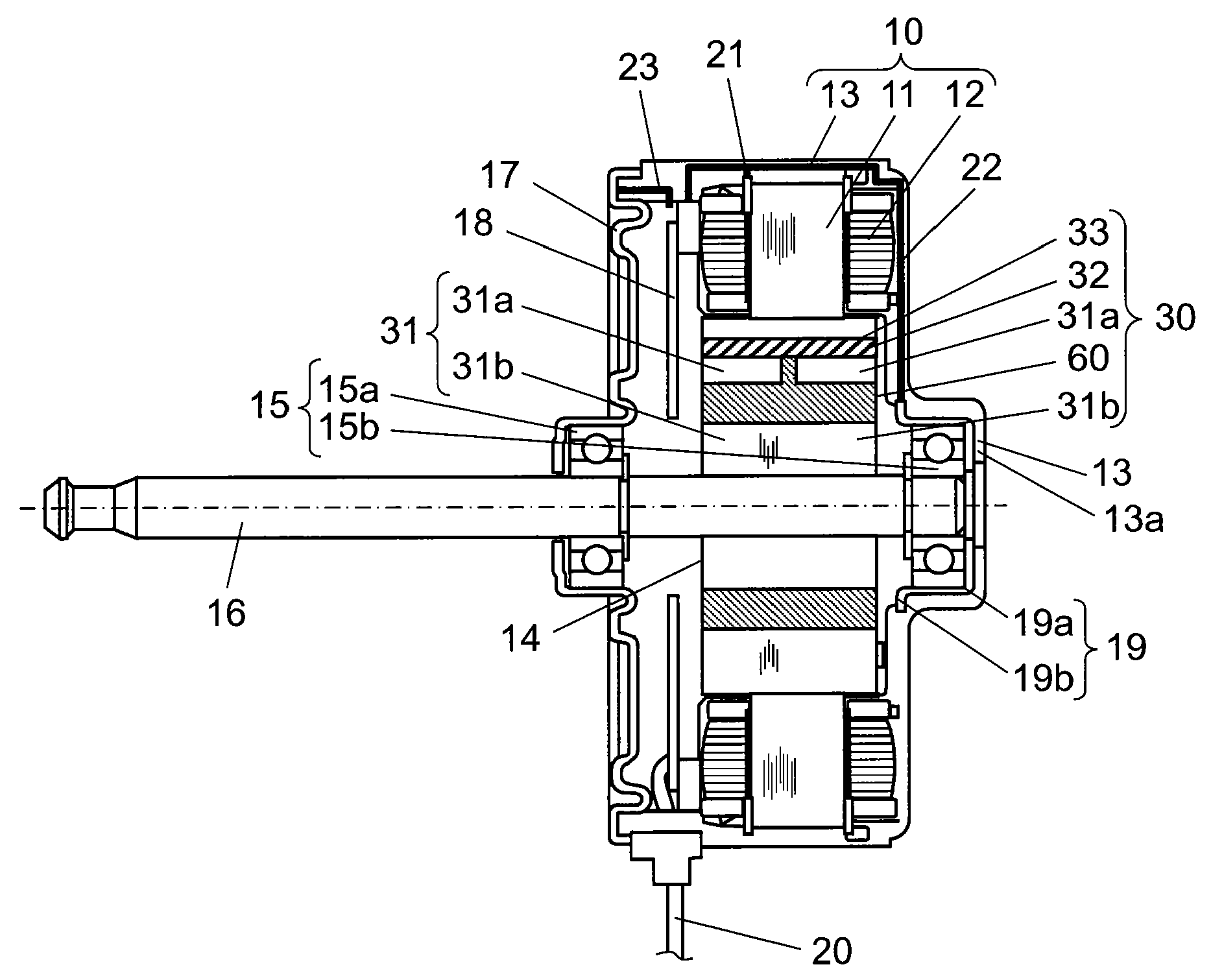
[0058]FIG. 1 is a structural drawing showing a section of an electric motor according to the first exemplary embodiment of this invention. In this embodiment, description is provided of a brushless motor as an example of the electric motor mounted inside an air conditioner representing an electric device for driving a blower fan. The example described in this embodiment is an inner-rotor type electric motor having a rotor arranged inside a stator in a freely rotatable manner.

[0059]In FIG. 1, stator coil 12 is wound around stator core 11 with resin 21 interposed between them as an insulator for insulating stator core 11. Stator core 11 of this structure is molded with insulation resin 13 used as a molding material together with other fixing members. In this embodiment, stator 10 having an outward appearance of generally a cylindrical shape is formed of these members by integrally molded in this fashion.

[0060]Rotor 14 is inserted into stator 10 with a gap provided between them. Rotor ...

second exemplary embodiment

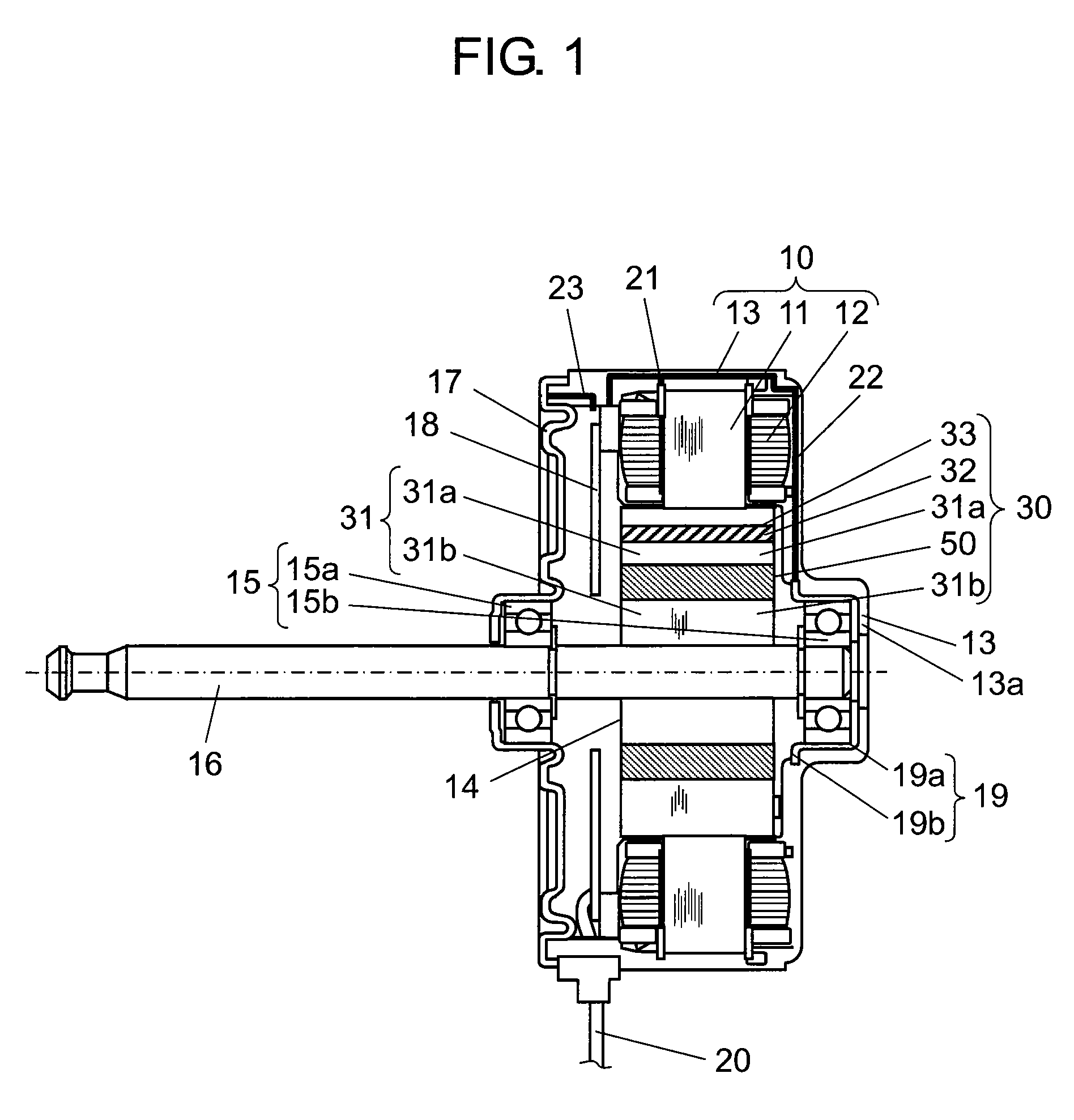
[0084]FIG. 4 is a structural drawing showing a section of a brushless motor according to second exemplary embodiment of the present invention. FIGS. 5A and 5B illustrate a top view of rotating body 30 of the brushless motor and a section taken along the line 5B-5B of the same according to the second embodiment of this invention. When compared with the first embodiment, the brushless motor representing an electric motor of this embodiment comprises rotating body 30 provided with dielectric layer 60 of a different shape than that of dielectric layer 50 of the first embodiment. All components other than dielectric layer 60 in this embodiment are generally similar to those of the first embodiment, and details of them will be skipped.

[0085]As shown in FIGS. 4, 5A and 5B, rotating body 30 of this embodiment comprises outer iron core 31a located at the outermost side having a plurality of insertion holes 33, dielectric layer 60, and inner iron core 31b, which are arranged in this order tow...

third exemplary embodiment

[0105]As a third exemplary embodiment, description is provided in detail of a structure of an air conditioner's indoor unit as an example of the electric device according to the present invention.

[0106]FIG. 14 is a structural drawing of the electric device according to the third embodiment of this invention.

[0107]In FIG. 14, air conditioner's indoor unit 210 is provided with electric motor 201 mounted inside casing 211. Electric motor 201 has cross-flow fan 212 attached to its rotary shaft. Electric motor 201 is driven by motor driving unit 213. Electric motor 201 rotates when energized by motor driving unit 213, which in turn rotates cross-flow fan 212. The rotation of cross-flow fan 212 delivers the air conditioned by a heat exchanger (not shown) inside the indoor unit into the room. Any of the electric motors in the above-described first and second embodiments is adaptable for use as electric motor 201.

[0108]The electric device of the present invention comprises the electric moto...


PUM


Abstract

Provided is an electric motor driven by an inverter of PWM method, and devised to retard electrolytic corrosion in a bearing. A rotating body of a rotor comprises an outer iron core configuring an outer peripheral portion of the rotating body, an inner iron core configuring an inner peripheral portion connected to a shaft, a dielectric layer disposed between the outer iron core and the inner iron core, a plurality of insertion holes penetrating the outer iron core in the axial direction, and permanent magnets inserted individually in the plurality of insertion holes. It thus becomes possible to increase impedance of the rotor side (inner ring side of bearing) to approximate it to impedance of the stator side (outer ring side of the bearing) to thereby bring high frequency potentials balanced between the inner ring side and the outer ring side of the bearing, so as to provide the electric motor that retards electrolytic corrosion liable to occur in the bearing, and an electric device equipped with the same.

Description

TECHNICAL FIELD[0001]The present invention relates to an electric motor provided with a rotor having permanent magnets inserted individually into insertion holes, and more particularly to an improvement made in the electric motor to retard electrolytic corrosion that occurs in a bearing.BACKGROUND ART[0002]There are increasing cases in recent years where electric motors are adapted to driving systems that use inverters of pulse width modulation method (hereinafter referred to as PWM method). In the case of inverter driving such as the PWM method, there appears a potential difference between an outer ring and an inner ring of a bearing (hereinafter referred to as a shaft voltage) since an electric potential at a neutral point of a coil winding does not become zero. The shaft voltage includes high frequency components due to switching, and a small electric current flows in the bearing that causes electrolytic corrosion inside the bearing when the shaft voltage reaches a dielectric bre...

Claims


Application Information

Patent Timeline
Patent Type & Authority Patents(United States)
IPC IPC(8): H02K11/00H02K1/30H02K5/173H02K21/14H02K1/27
CPCH02K5/1732H02K11/0005H02K1/276H02K11/0089H02K11/40
Inventor WATANABE, AKIHIKOHASEGAWA, TAKEHIKOMIZUKAMI, HIROFUMIKADO, HARUHIKOKONDO, GENKI
Owner PANASONIC CORP
Why Eureka
Try Eureka