Artificial hip joint

a hip joint and artificial technology, applied in hip joints, prostheses, medical science, etc., can solve the problems of inducing a rupture in the head and likely damage, and achieve the effect of reducing the stress generated in the head, ensuring the fixing strength of the head, and sufficient length

Inactive Publication Date: 2015-10-01
KYOCERA MEDICAL CORP
View PDF40 Cites 7 Cited by
  • Summary
  • Abstract
  • Description
  • Claims
  • Application Information

AI Technical Summary

Benefits of technology

[0035]According to the invention, an inner circumferential portion of a sleeve makes contact with an outer circumferential surface of a neck portion, and an outer circumferential portion of the sleeve makes contact with an inner circumferential surface of a head at a region farther away than an opening portion of a concavity in an insertion direction. Thus, a stress concentration portion generated in the head can be moved to a site having the cross-sectional area larger than the opening portion of the head. Accordingly, it is possible to provide an artificial hip joint in which stress generated in the head can be reduced by mitigating concentration of stress. Since the length of fit of the outer circumferential surface of the neck portion and the inner circumferential portion of the sleeve which is in contact therewith can achieve a sufficient length, it is possible to ensure fixing strength of the head with respect to the neck portion. Accordingly, it is possible to realize miniaturization of the head by lowering the overall height of the head to the extent that the minimal necessary sliding area of the head can be obtained. Since the inner circumferential portion of the sleeve becomes a guide when the head is mounted on the neck portion, it is possible to lower the possibility that the head and the neck portion fit obliquely.
[0036]In addition, according to the invention, the inner circumferential portion of the sleeve makes contact with the outer circumferential surface of the neck portion, the outer circumferential portion of the sleeve makes contact with the inner circumferential surface of the head, and a slit extending in the insertion direction from one end portion of the sleeve is formed between the inner circumferential portion and the outer circumferential portion thereof. Accordingly, it is possible to mitigate concentration of stress by moving the stress concentration portion generated in the head to the site having the cross-sectional area larger than the opening portion of the head.
[0037]Furthermore, according to the invention, the sleeve is realized by a multi-layer structure in which a plurality of sleeve sections are stacked. Accordingly, sliding is generated at interfaces of the plurality of sleeve sections, and thus, it is possible to mitigate stress generated in the head.
[0038]Furthermore, according to the invention, the inner circumferential portion of the sleeve makes contact with the outer circumferential surface of the neck portion, the outer circumferential portion of the sleeve makes contact with the inner circumferential surface of the concavity, and a flange portion makes contact with a peripheral surface of the opening portion of the concavity. Accordingly, it is possible to mitigate stress by causing the concentration of stress generated in the vicinity of the opening portion of the head to disperse in a direction along the outer circumferential portion of the sleeve and a direction along the flange portion.
[0039]Furthermore, according to the invention, the sleeve is made of Ti or a Ti alloy suitable for corrosion resistance and malleability. Thus, it is possible to improve strength of a caput of the artificial hip joint, and simultaneously, it is possible to improve a fitting force of the caput and the neck.

Problems solved by technology

However, the ceramic head has a problem in that damage is likely to occur due to incompatibility between the neck portion at the tip portion of the metallic stem to be joined and the concavity formed in the head.
However, in practice, when the neck portion of the stem is inserted into the concavity formed in the ceramic head, stress distribution in a concavity section of the head becomes irregular due to even incompatibility caused by a slight scratch in the neck portion, leading to a problem of inducing a rupture in the head caused by local stress concentration.

Method used


Image

  • Artificial hip joint
  • Artificial hip joint
  • Artificial hip joint

Examples


embodiment 1

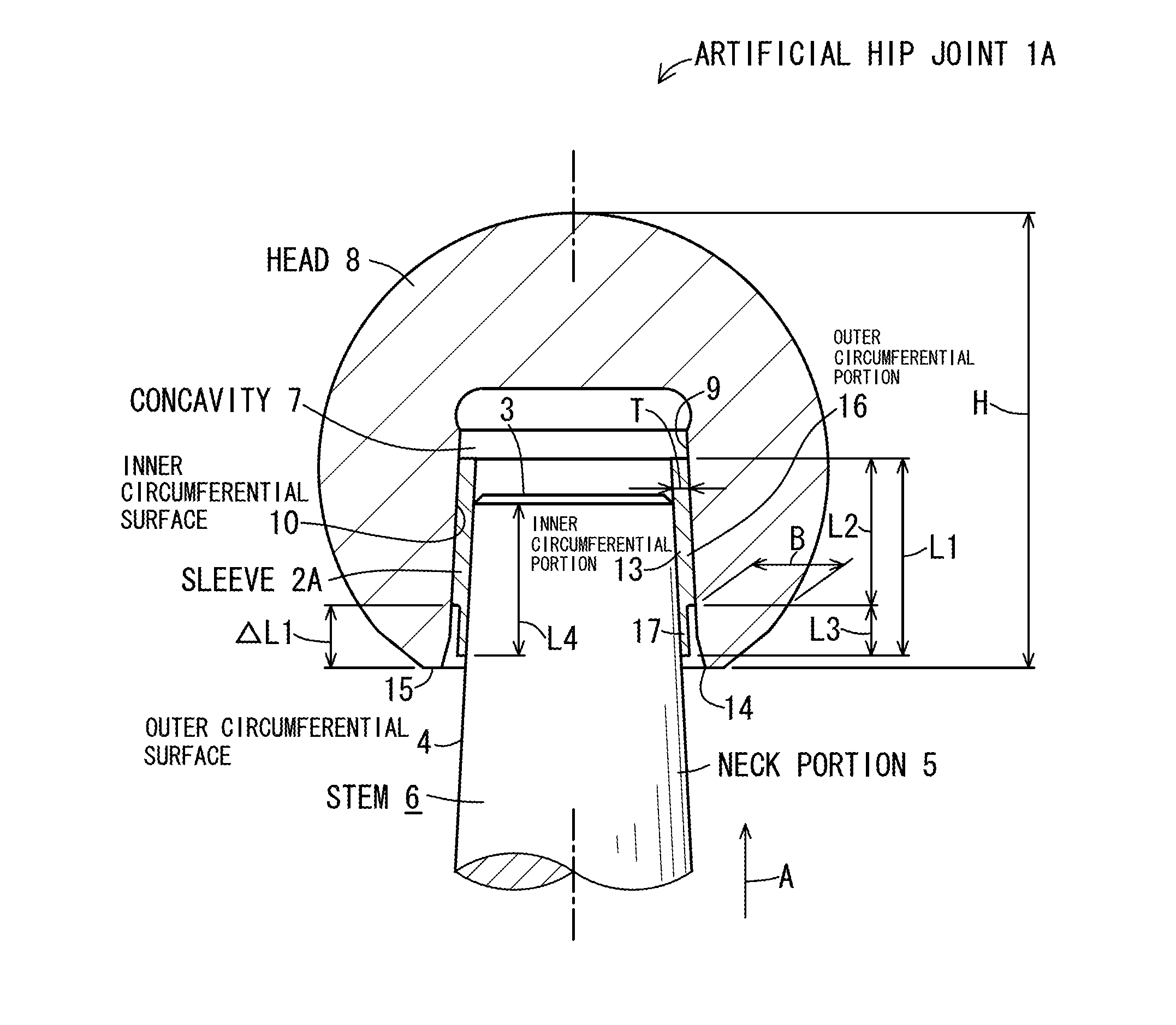
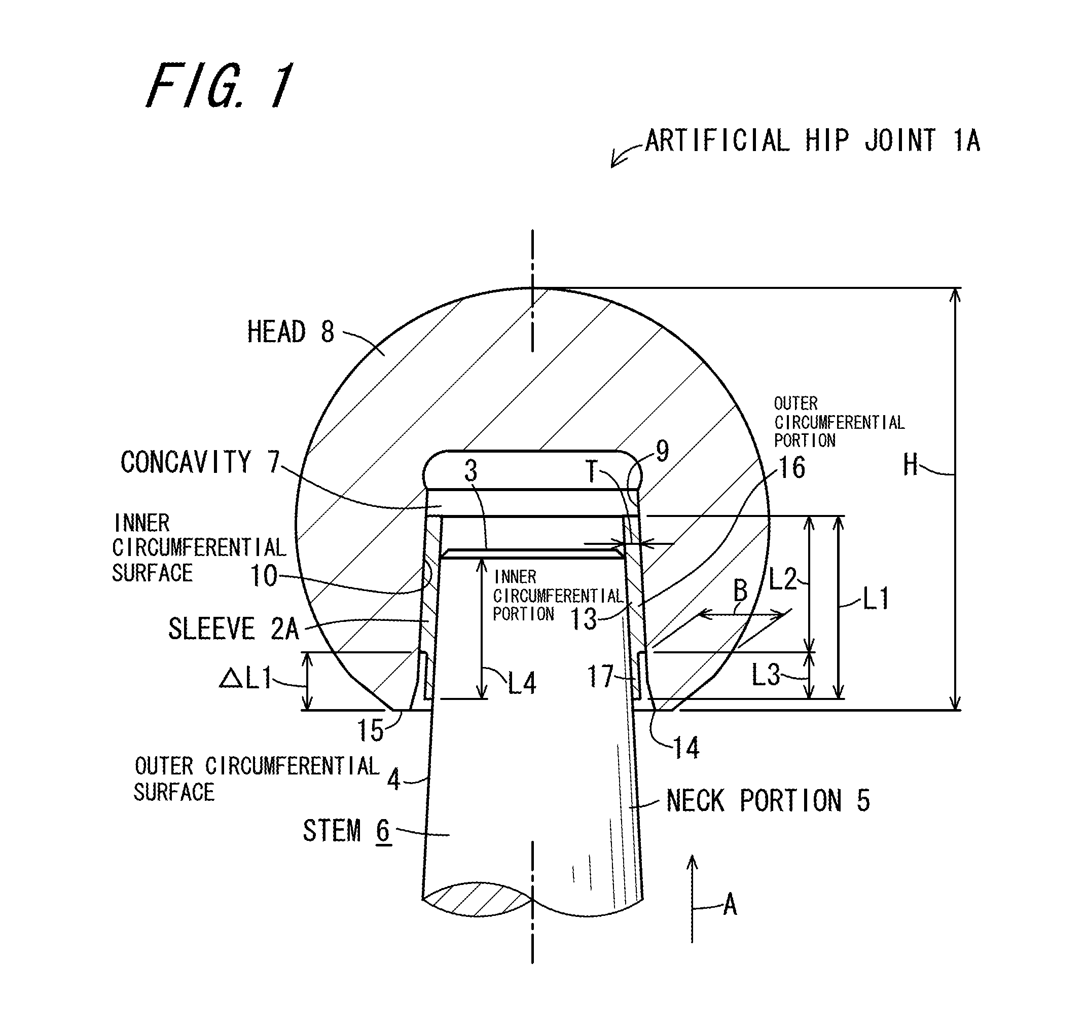
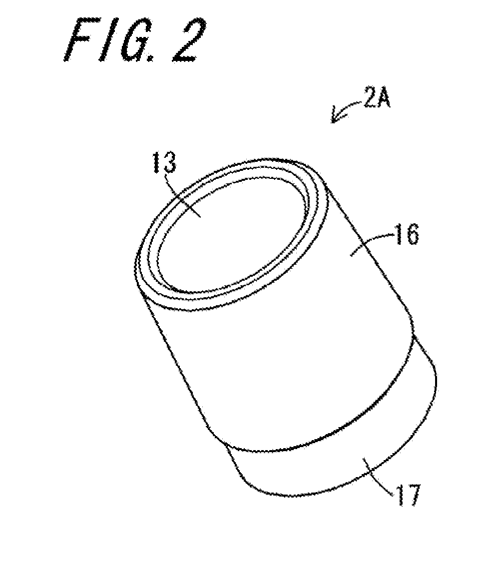
[0058]FIG. 1 is a cross-sectional view illustrating an artificial hip joint 1A according to Embodiment 1 of the invention, and FIG. 2 is a perspective view of a sleeve 2A which is used in the artificial hip joint 1A illustrated in FIG. 1. The artificial hip joint 1A of the present embodiment includes a stem 6, a head 8, and the sleeve 2A. The stem 6 has a neck portion 5 which has a truncated conical outer circumferential surface 4 decreased in diameter toward a tip 3 thereof. The head 8 is provided with a concavity 7 in which the neck portion 5 is inserted, and the head 8 has an inner surface 9 defining the concavity 7 which inner surface includes a truncated conical inner circumferential surface 10 decreased in diameter toward an insertion direction A of inserting the neck portion 5. The sleeve 2A is inserted between the outer circumferential surface 4 of the neck portion 5 inserted into the concavity 7, and the inner circumferential surface 10 of the head 8.

[0059]The stem 6 is mad...

example 1

Analysis Example 1

[0068]FIG. 3 is a diagram illustrating a stress analysis model of an artificial hip joint. FIG. 4 is a stress distribution diagram showing an analysis result of Example 1 simulating the artificial hip joint 1A illustrated in FIG. 1. FIG. 5 is a stress distribution diagram showing an analysis result of Comparison Example 1. FIG. 6 is a stress distribution diagram showing an analysis result of Comparison Example 2. In each diagram, the same reference numerals are assigned to portions corresponding to those of the artificial hip joint 1A in FIG. 1.

[0069]In the artificial hip joint 1A according to Embodiment 1, the inventors have carried out a stress analysis by using a finite element method (abbreviated to FEM) in order to identify the stress generated when an external force is applied to the head 8. As an analysis method, the stress analysis model illustrated in FIG. 3 is used. As an analysis target, the analysis model simulating the artificial hip joint 1A in FIG. 1...

embodiment 2

[0078]FIG. 7 is a cross-sectional view illustrating an artificial hip joint 1B according to Embodiment 2 of the invention. FIG. 8 is a perspective view of a sleeve 2B which is used in the artificial hip joint 1B. The same reference numerals are assigned to portions corresponding to those in Embodiment 1 described above.

[0079]The artificial hip joint 1B of the present embodiment, in common with Embodiment 1, includes the stem 6, the head 8, and the sleeve 2B. The stem 6 has the neck portion 5 which has the truncated conical outer circumferential surface 4 decreased in diameter toward the tip thereof. The head 8 is provided with the concavity 7 in which the neck portion 5 is inserted, and the head 8 has the inner surface defining the concavity 7 which inner surface includes the truncated conical inner circumferential surface 10 decreased in diameter toward the insertion direction of inserting the neck portion 5. The sleeve 2B is inserted between the outer circumferential surface 4 of ...


PUM


Abstract

An artificial hip joint includes a stem having a neck portion which has a truncated conical outer circumferential surface decreased in diameter toward a tip thereof; a head provided with a concavity in which the neck portion is inserted, an inner surface of the concavity including a truncated conical inner circumferential surface decreased in diameter toward an insertion direction of inserting the neck portion; and a sleeve inserted between the outer circumferential surface of the neck portion and the inner circumferential surface of the head. The sleeve has an inner circumferential portion which makes contact with the outer circumferential surface of the neck portion, and an outer circumferential portion which makes contact with the inner circumferential surface of the head, a starting end of the outer circumferential portion being located at a position retracting from an opening portion of the concavity in the insertion direction.

Description

TECHNICAL FIELD[0001]The present invention relates to an artificial hip joint in which a neck portion of a stem fits a tapered concavity of a head so as to join the head and the stem together.BACKGROUND ART[0002]Conventionally, an artificial hip joint is made of metal such as stainless steel, a cobalt-chromium alloy, or a titanium alloy, and has a stem inserted into and fixed to a thighbone, and a ceramic head, wherein the head and the stem are fixed in an integral manner or by performing taper-fitting, and a polyethylene cup is fixed onto an acetabular cartridge side in which the head is received.[0003]The heads mostly have a taper-fitting structure so as to be fixed to a neck portion formed at a tip portion of a metal stem. The head is configured to be adjustable in length of fit (also referred to as “a neck offset”) when being attached to the stem, by changing the depth or the inner diameter of a concavity which is also called a tapered hole.[0004]In consideration of combination ...

Claims


Application Information

Patent Timeline
Patent Type & Authority Applications(United States)
IPC IPC(8): A61F2/36
CPCA61F2/3609A61F2310/00023A61F2210/0076A61F2002/365A61F2002/30332A61F2002/30474A61F2002/30571
Inventor WAKIYAMA, MIYOSHIMOZONO, TAKAYOSHI
Owner KYOCERA MEDICAL CORP
Why Eureka
Try Eureka