Preform having a variable thickness around a main axis

a technology of a main axis and a thickness, which is applied in the field of container manufacturing, can solve the problems of difficult diaphragm inversion and requires an important effort to be applied, and achieve the effect of facilitating the inversion thereo

Inactive Publication Date: 2017-08-24
SIDEL PARTICIPATIONS SAS
View PDF1 Cites 2 Cited by
  • Summary
  • Abstract
  • Description
  • Claims
  • Application Information

AI Technical Summary

Benefits of technology

[0009]It is another purpose of the invention to propose a preform having an enhanced design which, when blown into a container provided with an invertible diaphragm, facilitates inversion thereof.
[0011]When the preform is blown into a container provided with an invertible diaphragm, the bottom of varying thickness gives birth, on the container, to a diaphragm with a mechanical resistance varying around the axis, which facilitates inversion thereof.

Problems solved by technology

In practice, inversion of the diaphragm is rather difficult and requires an important effort to be applied on the container bottom.
However, tests conducted on a container made from such a preform revealed that the effort to be applied on the container bottom to achieve inversion of the diaphragm is still important and therefore requires a large mechanical pusher to be mounted along the container manufacturing line.

Method used


Image

  • Preform having a variable thickness around a main axis
  • Preform having a variable thickness around a main axis
  • Preform having a variable thickness around a main axis

Examples


Embodiment Construction

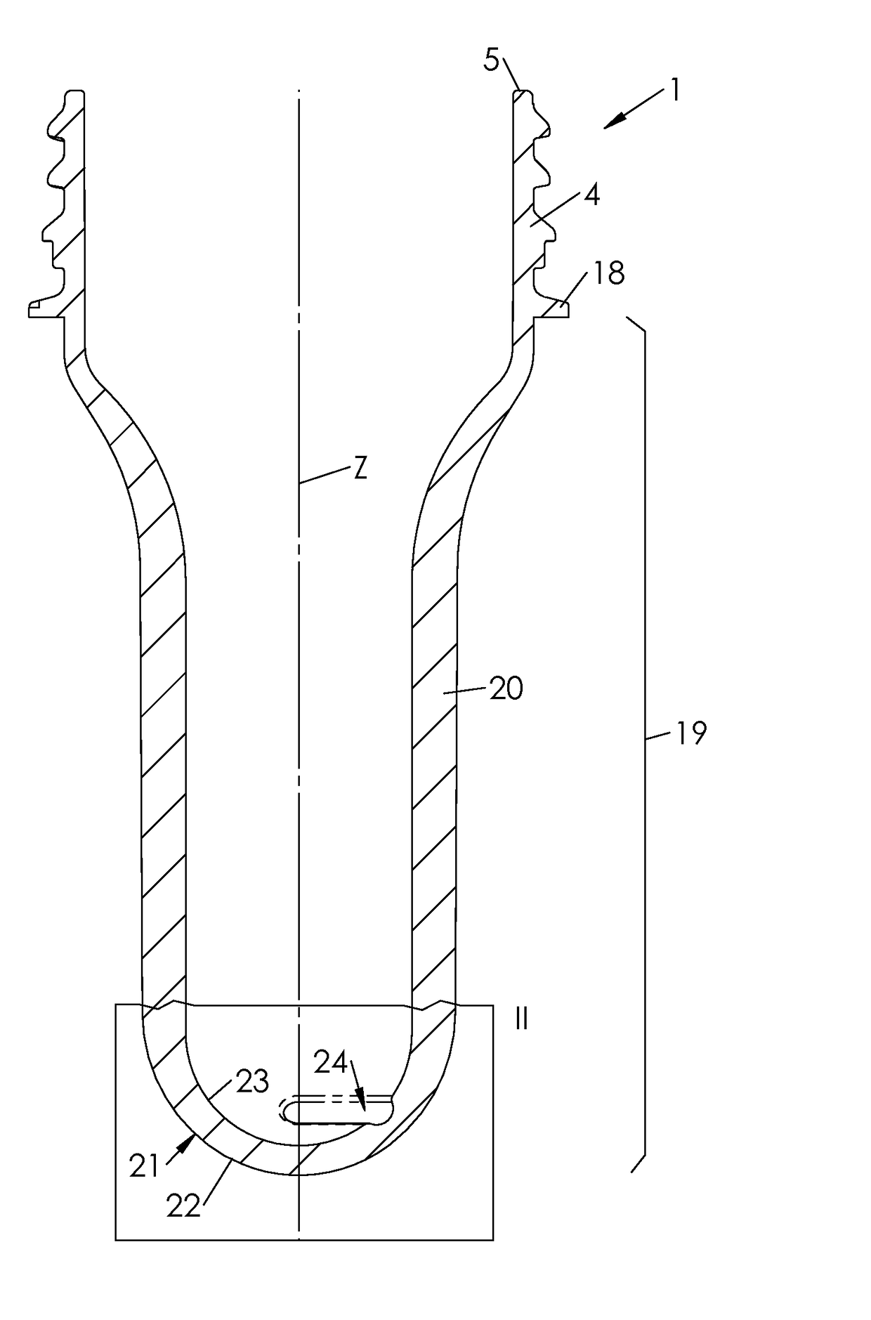
[0028]Shown on FIG. 1 is a preform 1 from which a container 2 such as a bottle is to be formed by blow molding or stretch blow molding within a mold 3.

[0029]The container 2 includes an open cylindrical threaded upper portion or neck 4, which terminates, at an upper end thereof, by an opening or mouth 5. Below the neck 4, the container 2 includes a shoulder 6 of increasing diameter in a direction opposite to the neck 4.

[0030]Below the shoulder 6, the container 2 has a sidewall 7 which is substantially cylindrical around a container main axis Z. The sidewall 7 may, as depicted in FIG. 5 and FIG. 6, include annular stiffening ribs 8 capable of resisting thermal and mechanical stresses undergone by the container 2 during filling, capping and subsequent handling.

[0031]At a lower end of the sidewall 7, the container 2 has a base 9 which closes the container 2 and allows it to be normally put on a planar surface such as a table when used by a final customer.

[0032]The container base 9 inclu...


PUM

PropertyMeasurementUnit
angleaaaaaaaaaa
angleaaaaaaaaaa
angleaaaaaaaaaa

Abstract

Preform (1) made of a plastic material for the manufacturing of a container (2) by blow molding or stretch-blow molding, the preform (1) including a sidewall (20) extending along a main axis (Z), an open neck (4) and a substantially hemispherical closed bottom (21) having a thickness (T) which varies at least locally around the main axis (Z).

Description

FIELD OF THE INVENTION[0001]The invention generally relates to the manufacturing of containers, such as bottles, which are produced by blow molding or stretch-blow molding from preforms made of a plastic material (such as PET). More specifically, the invention relates to a preform for the manufacturing of a container.BACKGROUND OF THE INVENTION[0002]A conventional preform, which is generally injected molded but might also be compression molded, is comprised of an open cylindrical threaded upper portion or neck, which terminates at a lower end in an annular protrusion, forming a support collar (used to carry the perform and the container at different steps of the manufacturing and packaging processes), a wall portion of generally cylindrical shape, which extends below the support collar, and a closed rounded bottom portion which extends below the wall portion.[0003]During a conventional blow molding process, the preform undergoes both an axial (or length) stretch and a radial (or hoo...

Claims


Application Information

Patent Timeline
Patent Type & Authority Applications(United States)
IPC IPC(8): B29B11/14
CPCB29B11/14B29B2911/14332B29B2911/14013B29L2031/7158B29C49/0073B29K2067/003B29K2105/258B29B2911/14486B29C49/4273B29C49/06B29C2949/28B29C2949/26B29C2949/24B29C2949/22B29C2949/072B29C2949/078B29C49/071B29C2949/0715B29C49/42802B29C49/42808B29C49/4283B29C49/42832B29C2949/20B29C2949/0725
Inventor BUNEL, CHRISTOPHE
Owner SIDEL PARTICIPATIONS SAS
Why Eureka
Try Eureka