

Container provided with a curved invertible diaphragm
- Summary
- Abstract
- Description
- Claims
- Application Information
AI Technical Summary
Benefits of technology
Problems solved by technology
Method used
Image

Examples
first embodiment
[0103]In a first embodiment, the outer limit 42 of the upper end surface 40 is also a peripheral edge of the pusher 26. In this case, the pusher 26 has a cylindrical lateral wall 43, which extends vertically from the outer limit 42. As depicted in the detail view of FIG. 13, the outer limit 42 should preferably not be sharp but instead be provided with a fillet radius to prevent damage to the diaphragm 11 when achieving inversion.
[0104]To achieve inversion of the diaphragm 11 from its downwardly-protruding position to its inwardly-protruding position, the pusher 26 (together with the rod 30 and the piston 29) is moved from its rest position, in which the pusher 26 is spaced from the diaphragm 11 (FIG. 12 and FIG. 13) to its active position, in which the pusher 26 protrudes inside the container 1 (FIG. 14 and FIG. 15).
[0105]As soon as the pusher 26 comes into abutment against the diaphragm 11, the pusher 26 exerts on the diaphragm 11 an inwardly (or upwardly) oriented inversion effor...
second embodiment
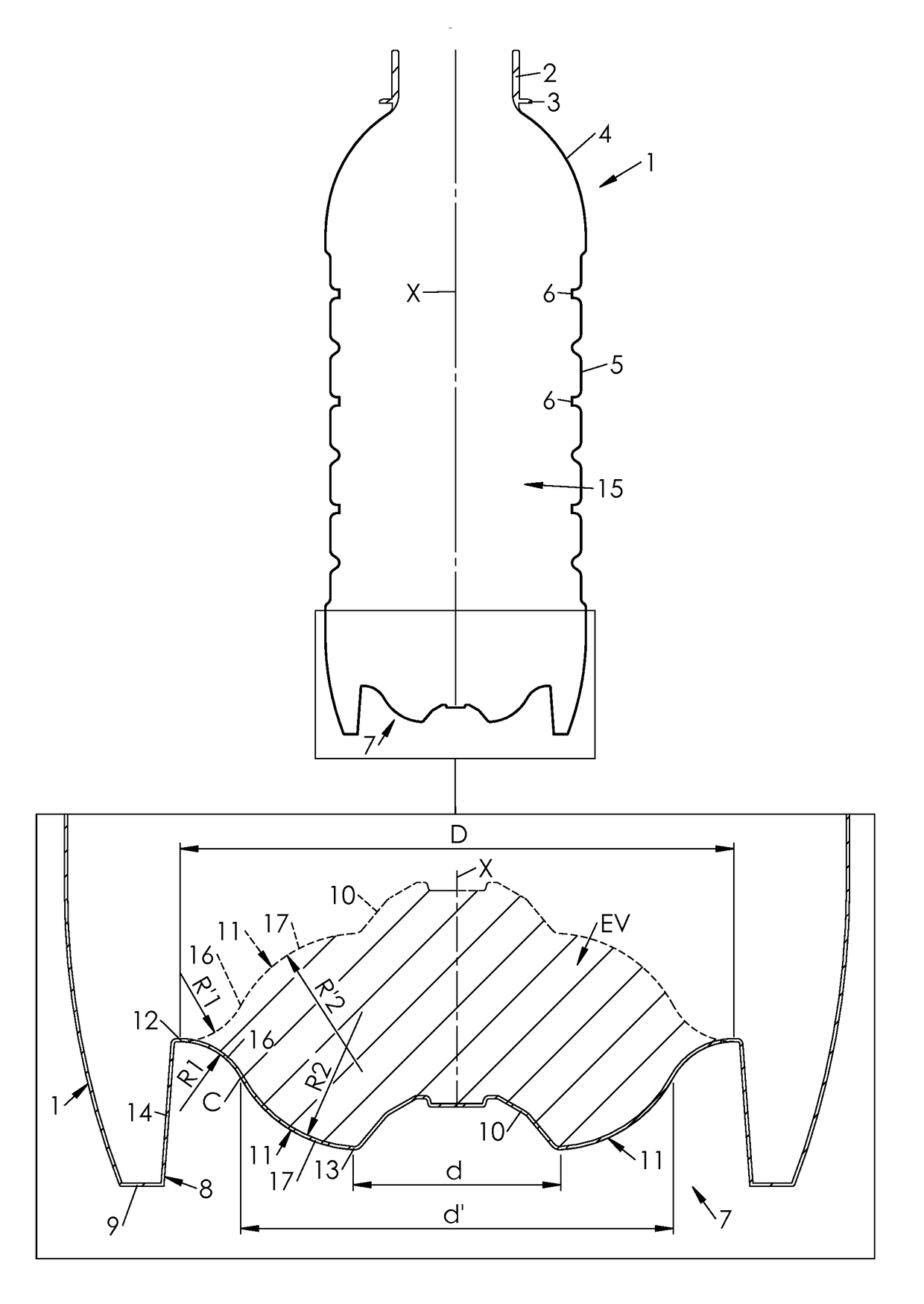
[0110]In this second embodiment, the peripheral surface 44 extends from the outer limit 42 down to an outer edge 45 (preferably provided with a fillet radius to prevent damage to the diaphragm 11) and the pusher 26 still has a cylindrical lateral wall 43, an outer diameter (noted d″) of which is substantially equal to the outer diameter D of the diaphragm 11.
[0111]Inversion of the diaphragm 11 is achieved in the same manner as disclosed hereinbefore. The presence of the peripheral surface 44 provides even greater control of the inversion of the diaphragm 11, the peripheral surface 44 comes into abutment against the outer portion 16 of the diaphragm 11 and hence provides support thereto in its inwardly-protruding position.
[0112]In a third embodiment depicted on FIG. 18 and FIG. 19, having features added to the second embodiment, which has just been disclosed, the pusher 26 further has a frusto-conical lateral skirt 46 (instead of the cylindrical wall 43) complementary in shape to the...
PUM
 Abstract
Description
Claims
Application Information