Microscope and Component for Multi-beam Scanning

Active Publication Date: 2017-10-12
CARL ZEISS MICROSCOPY GMBH
View PDF0 Cites 0 Cited by
  • Summary
  • Abstract
  • Description
  • Claims
  • Application Information

AI Technical Summary

Benefits of technology

[0010]It is the object of the invention to implement a beam multiplier with preferably

Problems solved by technology

However, it is disadvantageous that all of the partial bundles are fo

Method used


Image

  • Microscope and Component for Multi-beam Scanning
  • Microscope and Component for Multi-beam Scanning
  • Microscope and Component for Multi-beam Scanning

Examples


Embodiment Construction

[0024]It is to be understood that the figures and descriptions of the present invention have been simplified to illustrate elements that are relevant for a clear understanding of the present invention, while eliminating, for purposes of clarity, many other elements which are conventional in this art. Those of ordinary skill in the art will recognize that other elements are desirable for implementing the present invention. However, because such elements are well known in the art, and because they do not facilitate a better understanding of the present invention, a discussion of such elements is not provided herein.

[0025]The present invention will now be described in detail on the basis of exemplary embodiments.

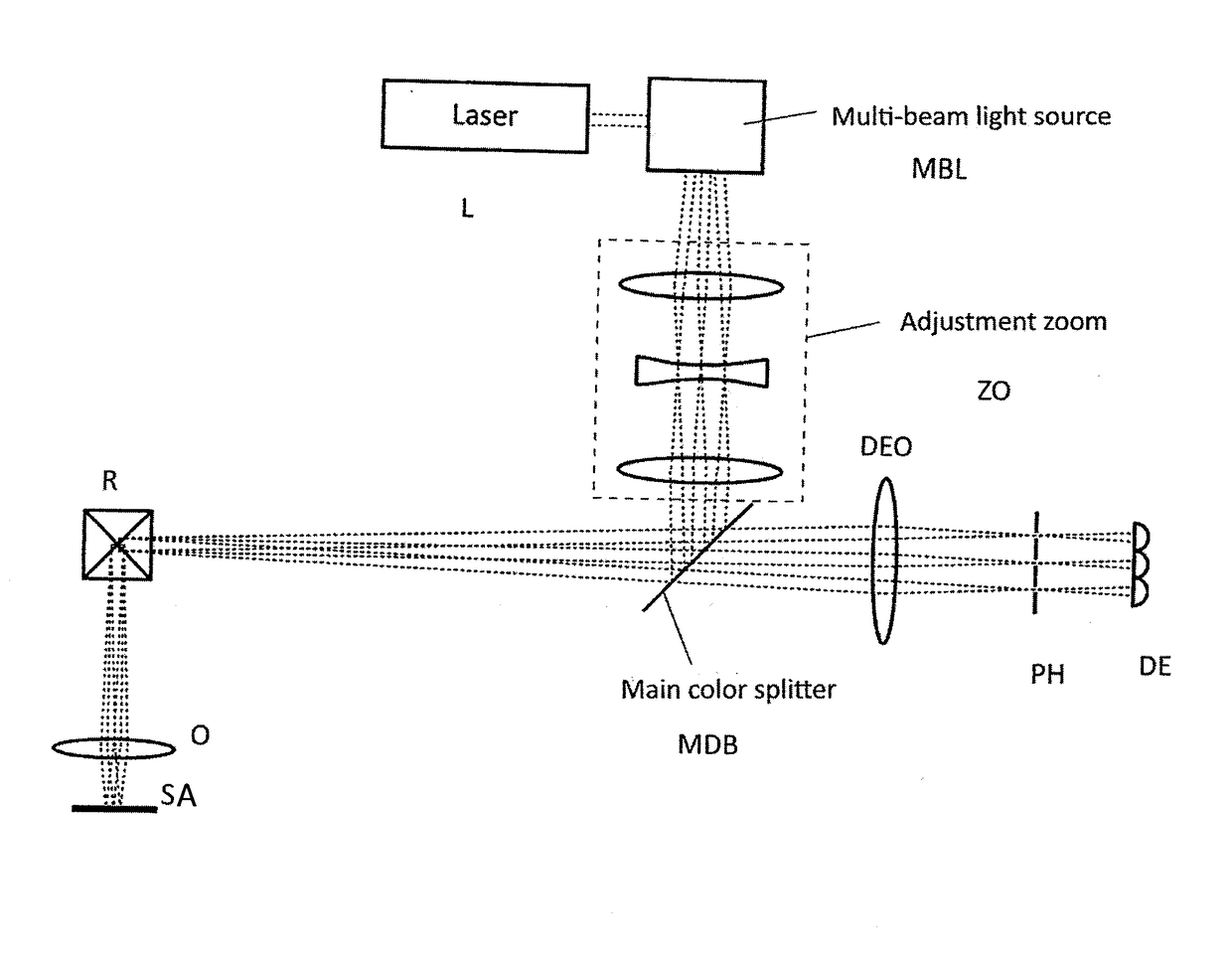
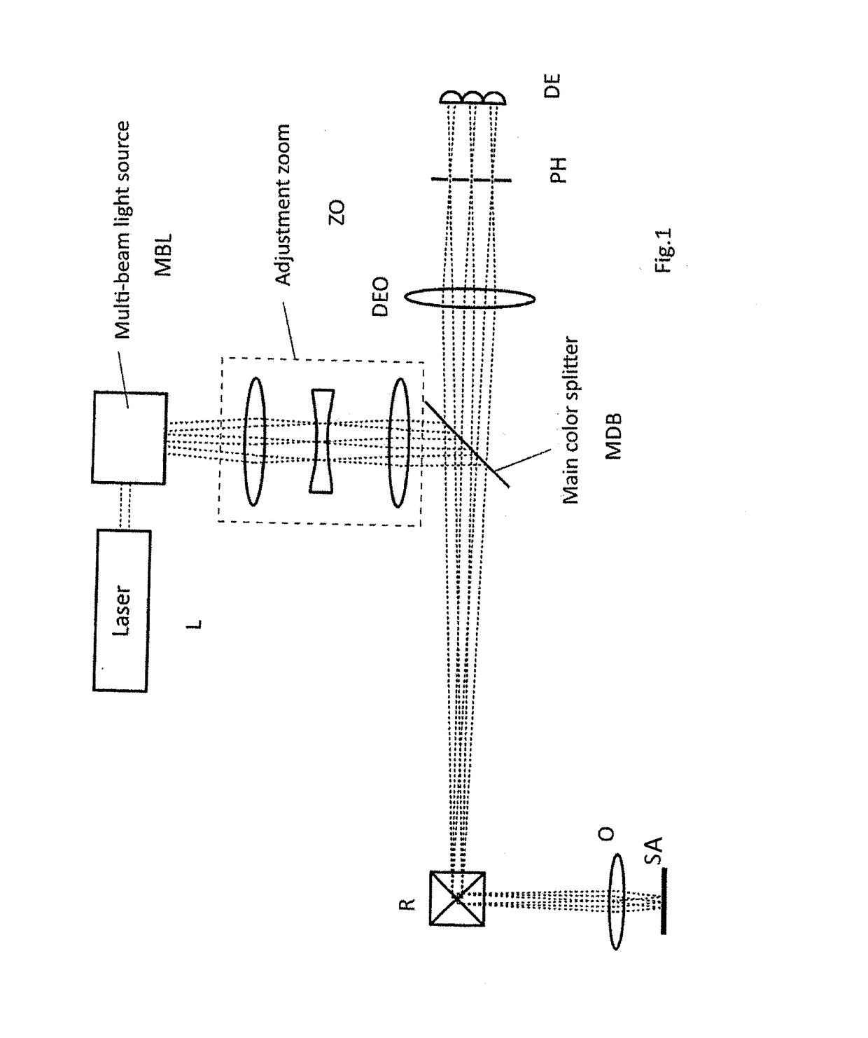
[0026]First, FIG. 1 shows a basic optical arrangement in a microscope with a multiple-beam light source. The light of a laser L proceeds to an arrangement for beam multiplication MBL as will be described in more detail in the following for the present invention.

[0027]The light ...


PUM


Abstract

A laser-scanning microscope having an illumination-beam path and a detection-beam path and a microscope objective. A component for generating a plurality of scanning beams from at least one illumination beam is located in the illumination-beam path. A wedge-shaped, light-transmitting first component part provided in the illumination beam path generates spatially offset partial beams, the scanning beams being generated at the first component part by multiple reflections at an at least partially partially-reflecting surface. The microscope has a one-dimensional scanner for moving the scanning beams over a sample in the illumination beam path. The scanning beams have at least partially relative to one another a non-zero angle upstream of the objective in the illumination direction. The scanning beams can intersect at least partially in the objective pupil of the microscope objective. Additional compensation elements are provided for the scanning beams to compensate for a spectral dispersion and/or the beam direction.

Description

[0001]The present application claims priority to German Patent Application No. DE 10 2014 003 773.8 filed on Mar. 15, 2014, the disclosure of which is incorporated herein by reference in its entirety.FIELD OF THE INVENTION[0002]Arrangements for beam multiplication are known from publications and patents.[0003]It is noted that citation or identification of any document in this application is not an admission that such document is available as prior art to the present invention.[0004]An advantageous application is carried out in laser scanning microscopes (LSMs) because, in this way, the scan speed is increased compared to single-point scanning. A beam can be split either by guiding separate beam parts in different directions (geometric splitting) or by using a beam splitter and further utilizing the reflected and transmitted component of the beam (physical splitting). Examples for both principles are mentioned, e.g., in Naumann / Schröder, “Optical Components [Bauelemente der Optik]”, ...

Claims


Application Information

Patent Timeline
IPC IPC(8): G02B21/00
CPCG02B21/002G02B21/0032G02B21/06G02B27/10
Inventor WALD, MATTHIAS
Owner CARL ZEISS MICROSCOPY GMBH
Why Eureka
Try Eureka