Container provided with a curved invertible diaphragm

a container and invertible technology, applied in the field of container manufacturing, can solve the problems of lack of rigidity once opened, bending of pressure panels, and inability to provide the necessary strength to withstand external stresses, and achieve the effect of greater stability

Active Publication Date: 2018-11-01
SIDEL PARTICIPATIONS SAS
View PDF6 Cites 0 Cited by
  • Summary
  • Abstract
  • Description
  • Claims
  • Application Information

AI Technical Summary

Benefits of technology

[0009]It is another object of the invention to propose a container provided with an invertible diaphragm capable of maintaining an inverted position and hence of withstanding high external stresses such as axial compression stresses.
[0017]The outer portion facilitates inversion of the diaphragm, while its inner portion provides rigidity in the inverted position, which prevents the diaphragm from sinking back. Pressure within the container is thereby maintained to a high value, providing high rigidity to the container. The important volume swept by the diaphragm between the outwardly-protruding position and the inwardly-protruding position increases the pressure inside the container to such a level that the loss of pressure due to temperature drop does not affect the rigidity of the container, which may hence be trustingly stacked or palletized.

Problems solved by technology

One main drawback of this type of container, however, is its lack of rigidity once opened.
Indeed, the pressure panels tend to bend under the grabbing force of the user, who should hence handle the container with care to avoid unintentional splashes.
Although such a structure has proved efficient to adapt to the changes in pressure inside the container and to maintain the shape of the container sidewall when the container stands alone, it does not provide the necessary strength to withstand external stresses such as vertical compression stresses undergone by the container when stacked or palletized.
Tests conducted on such a container showed that, once inverted to the inwardly-inclined position, the pressure panel does not maintain its position but tends to sink back under the pressure of the content.
When stacking or palletizing the containers, there is a risk for the lower containers to bend under the weight of upper containers, and hence a risk for the whole pallet to collapse.

Method used


Image

  • Container provided with a curved invertible diaphragm
  • Container provided with a curved invertible diaphragm
  • Container provided with a curved invertible diaphragm

Examples


Embodiment Construction

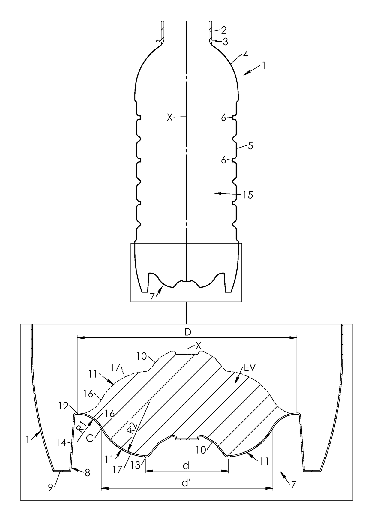
[0030]FIG. 1 shows a container 1 suitable for being filled with a hot product (such as tea, fruit juice, or a sports drink), “hot” meaning that the temperature of the product is greater than the glass transition temperature of the material in which the container 1 is made (about 80° C. in the case of PET).

[0031]The container 1 includes an upper open cylindrical threaded upper portion or neck 2, which terminates, at a lower end thereof, in a support collar 3 of greater diameter. Below the collar 3, the container 1 includes a shoulder 4 which is connected to the collar 3 through a cylindrical upper end portion of short length.

[0032]Below the shoulder 4, the container 1 has a sidewall 5 which is substantially cylindrical around a container main axis X. The sidewall 5 may, as depicted on FIG. 1, include annular stiffening ribs 6 capable of resisting stresses which would otherwise tend to make the sidewall 5 oval when viewed in a horizontal section (such a deformation is standard and cal...


PUM


Abstract

Disclosed is a container made of a plastic material, provided with a base including a standing ring forming a support flange and a diaphragm extending from the standing ring to a central portion, the diaphragm being capable of standing in an outwardly-inclined position. The diaphragm connects to the standing ring at an outer junction forming an outer articulation of the diaphragm. The diaphragm connects to the central portion at an inner junction forming an inner articulation of the diaphragm. The diaphragm is invertible with respect to the standing ring from the outwardly-inclined position to an inwardly-inclined position. In the outwardly-inclined position, the diaphragm has an outer curved portion and an inner curved portion of opposite curvatures.

Description

FIELD OF THE INVENTION[0001]The invention generally relates to the manufacturing of containers, such as bottles, which are produced by blow molding or stretch-blow molding from preforms made of plastic (mostly thermoplastic, e.g. PET) material. More specifically but not exclusively, the invention relates to the processing of hot-fill containers, i.e. containers filled with a hot pourable product (typically a liquid), the term “hot” meaning that the temperature of the product is greater than the glass transition temperature of the material in which the container is made. Typically, hot filling of PET containers (the glass transition temperature of which is of about 80° C.) is conducted with products at a temperature comprised between about 85° C. and about 100° C., typically at 90° C.BACKGROUND OF THE INVENTION[0002]Several types of containers are (at least allegedly) specifically manufactured to withstand the mechanical stresses involved by the hot filling and the subsequent changes...

Claims


Application Information

Patent Timeline
Patent Type & Authority Applications(United States)
IPC IPC(8): B65D1/02B65D79/00
CPCB65D1/0276B65D79/005B67C2003/226B65D79/0081B67C3/22
Inventor GODET, FLORIAN
Owner SIDEL PARTICIPATIONS SAS
Why Eureka
Try Eureka