
Method and system for monitoring quality of data transmission in idc network

a data transmission and data quality technology, applied in the field of network technologies, can solve the problems of affecting data quality, data loss, and bad decision that is generated according, and achieve the effects of avoiding the transmission of erroneous data, avoiding the occupation of unnecessary calculation resources, and avoiding the further calculation of erroneous data calculation results

Active Publication Date: 2017-08-24
TENCENT TECH (SHENZHEN) CO LTD
View PDF0 Cites 5 Cited by
  • Summary
  • Abstract
  • Description
  • Claims
  • Application Information

AI Technical Summary

Benefits of technology

The patent is about a method and system to monitor the quality of data transmission in an IDC network. This system can detect and prevent transmission of erroneous data that may waste network bandwidth resources. The system analyzes data sent by an application service node and received by a data storage node in real-time, calculates a data transmission quality index, and raises an exception alarm if the index does not meet a certain criterion. This helps avoid unnecessary data transmission and ensures accurate data processing, thereby preventing corrosive decisions based on erroneous data.

Problems solved by technology

In a transmission process of data, problems such as a data loss and a data transmission error that affect data quality may occur, and the quality of data has a critical effect on the correctness of a data calculation result.
An erroneous data calculation result may result in a bad decision that is generated according to the data calculation result.
If a data transmission problem occurs in a process of transmitting data from an application service node to a data storage node, the data in which an error has occurred is further transmitted to a data warehouse, which not only wastes network bandwidth resources, but also leads to the generation of an erroneous calculation result.

Method used


Image

  • Method and system for monitoring quality of data transmission in idc network
  • Method and system for monitoring quality of data transmission in idc network
  • Method and system for monitoring quality of data transmission in idc network

Examples


Embodiment Construction

[0028]In order to make the objectives, technical solutions, and advantages of the present disclosure more comprehensible, the present disclosure is described in further detail below with reference to embodiments and the accompanying drawings. It should be understood that, specific embodiments described herein are merely used to explain the present disclosure instead of limiting the present disclosure.

[0029]Unless the context clearly indicates otherwise, singular elements or components in the present disclosure may be in the plural and vice versa, which is not limited in the present disclosure. Although steps in the present disclosure are labeled with numbers, such numbers are not intended to limit the order of these steps. Unless the order of steps is explicitly stated or it is explicitly stated that a step needs to be performed on the basis of another step, the relative order of steps can be adjusted. It should be understood that as used herein, the term “and / or” involves and inclu...


PUM


Abstract

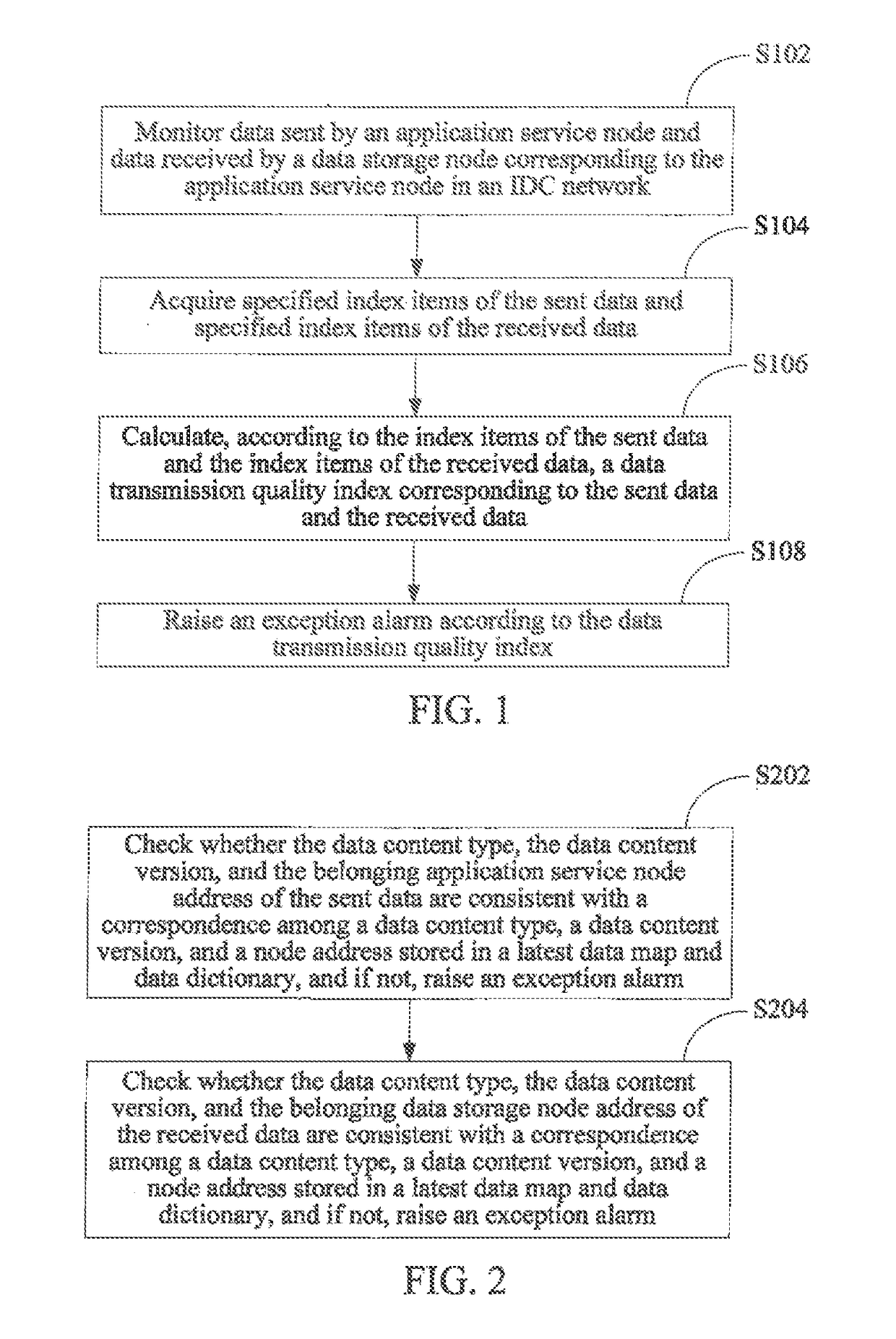
A method for monitoring quality of data transmission in an IDC network includes: monitoring data sent by an application service node and data received by a data storage node of the application service node in an IDC network; acquiring index items of sent data and index items of received data; calculating, according to the index items of sent data and the index items of received data, a data transmission quality index of the sent data and the received data; and raising an alarm according to the data transmission quality index. By contrast, transmission of erroneous data that causes a waste of network bandwidth resources can be avoided, and data calculation performed according to the erroneous data resulting in an erroneous data calculation result is further prevented; therefore, occupation of unnecessary calculation resources and a bad decision that is generated according to the erroneous data calculation result can be prevented.

Description

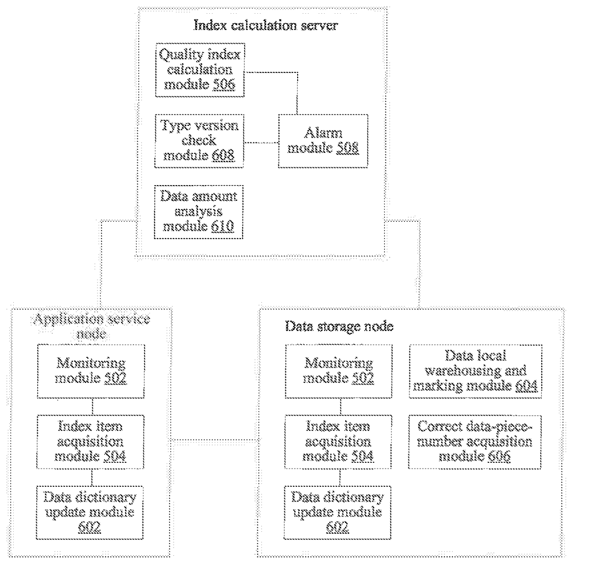
CROSS REFERENCE TO RELATED APPLICATION[0001]This application is a continuation of International Application No. PCT / CN2015 / 073202, filed on Feb. 16, 2015. This application claims the benefit and priority of Chinese Application No. 201410086058.2, filed Mar. 10, 2014. The entire disclosures of each of the above applications are incorporated herein by reference.FIELD OF THE TECHNOLOGY[0002]The present disclosure relates to the field of network technologies, and in particular, to a method and a system for monitoring quality of data transmission in an Internet data center (IDC) network.BACKGROUND OF THE DISCLOSURE[0003]An Internet data center is called IDC in short, and is a centralized facility base that provides devices for collecting, storing, processing, and sending data with operation and management. The IDC generally includes multiple servers, for example, an application service node that provide s an application service and a data storage node that stores data.[0004]An existing I...

Claims


Application Information

Patent Timeline
Patent Type & Authority Applications(United States)
IPC IPC(8): H04L12/24H04L12/26
CPCH04L41/5025H04L43/0858H04L43/0847H04L41/5009
Inventor ZHOU, DONGXIANG
Owner TENCENT TECH (SHENZHEN) CO LTD
Learn More