Orthodontic self-ligating bracket

Active Publication Date: 2017-08-31
HIRSCH DYNAMICS HLDG AG
View PDF0 Cites 6 Cited by
  • Summary
  • Abstract
  • Description
  • Claims
  • Application Information

AI Technical Summary

Benefits of technology

[0016]In one embodiment, the clip is made of a Ni—Ti alloy. This alloy exhibits superelasticity, which keeps the elastic modulus of the clip substantially unchanged even with extended use. The clip can also be coated with a coating such Au/Rh, Pt/Rh and Pd/Rh, with Rh being an outermost layer. This coating minimizes the amount of Ni that leaches from the clip, and improves the aesthetics of the bracket when used in conjun

Problems solved by technology

A big drawback of this original design is there is nothing to secure the free end of the clip's labial side and therefore the arch wire can easily be displaced from the arch wire slot.
However, there is still insufficient restraint on the free end of the

Method used


Image

  • Orthodontic self-ligating bracket
  • Orthodontic self-ligating bracket
  • Orthodontic self-ligating bracket

Examples


Example

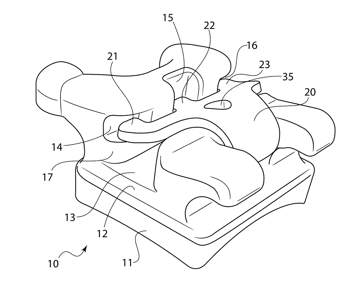
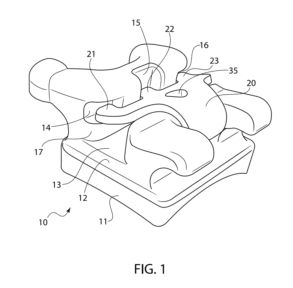
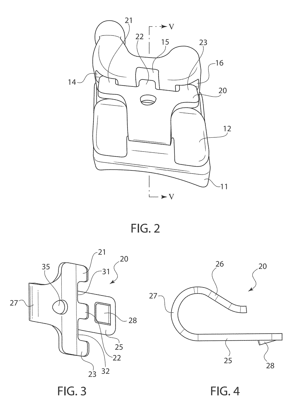
[0028]Referring now in detail to the drawings, FIGS. 1 and 2 show a self-ligating orthodontic bracket 10 comprising a base 11 and a bracket element 12, as well as a U-shaped ligating clip 20, shown in detail in FIGS. 3 and 4. Bracket element 12 has a mesial-distal slot 13 to accept an arch wire. Three cavities 14, 15, 16 are made at the gingival wall 17 of slot 13. Clip 20 has a first end with three protrusions 21, 22, 23 which engage indentations 14, 15, 16 when the clip 20 is in the closed position. This three-protrusion / three-indentation combination secures the clip firmly when it is subjected to force in the mesial-distal direction, providing an even distribution of forces on the arch wire during the active ligation stage. The three-protrusion / indentation formation provides substantially better distribution of force as compared with standard two-protrusion / indentation brackets. Clip 20 can be slid open and closed with the aid of an aperture 35 disposed behind protrusions 21, 22,...


PUM


Abstract

An orthodontic bracket has a base configured for attachment to a tooth surface, a bracket element with an arch wire slot attached to one side of the base, and a clip for securing the arch wire in the slot. The bracket element has a wall portion extending upward along one side of the arch wire slot. This wall portion has three indentations in a line parallel to the mesiodistal direction. There is a channel running entirely through the bracket element underneath the arch wire slot. The clip is substantially U-shaped and has three parallel protrusions shaped to fit within the three indentations of the wall portion, and a locking element. The clip is securable to the bracket by placing the clip through the channel and engaging the locking element onto the bracket element, and placing the protrusions into the indentations of the bracket element.

Description

BACKGROUND OF THE INVENTION[0001]1. Field of the Invention[0002]This invention relates to a self-ligating orthodontic bracket. In particular, the invention relates to an orthodontic bracket that has a particular three-pronged configuration that makes it easy to assemble yet remains securely fastened under tension.[0003]2. The Prior Art[0004]Self-ligating orthodontic brackets were developed to eliminate the need to secure the arch wire to the bracket with rubber bands. These brackets have a slot to receive the arch wire, and a clip is then snapped into place over the slot to keep the arch wire attached.[0005]U.S. Pat. No. 3,772,787 to Hanson discloses an early design of an active self-ligating bracket based on a flexible clip. New orthodontic brackets each comprise a body slotted for the reception of an arch wire and a U-shaped clip for retaining the arch wire in the slot. The clip is preferably of flat metal conforming to the shape of the body and is movable between two positions in...

Claims


Application Information

Patent Timeline
IPC IPC(8): A61C7/30A61C7/28A61C7/34A61C7/02
CPCA61C7/30A61C7/34A61C7/287A61C7/02
Inventor HIRSCH, MARKUS
Owner HIRSCH DYNAMICS HLDG AG
Why Eureka
Try Eureka