Textile component

Inactive Publication Date: 2006-09-28
STUDIO Z TEXTILES
View PDF9 Cites 12 Cited by
  • Summary
  • Abstract
  • Description
  • Claims
  • Application Information

AI Technical Summary

Benefits of technology

[0010] The present invention provides a textile component with all of the advantages of a jacquard or dobby woven fabric, as well as the additional advantages of improved aesthetics and a more efficient and cost effective way of attaching the fabric to an article. The pockets provide manufacturers with an easy way to provide inserts in components, and

Problems solved by technology

Upholstering is an inherently time consuming process.
It requires a great deal of labor in the cutting and sewing of t

Method used


Image

  • Textile component
  • Textile component
  • Textile component

Examples


Example

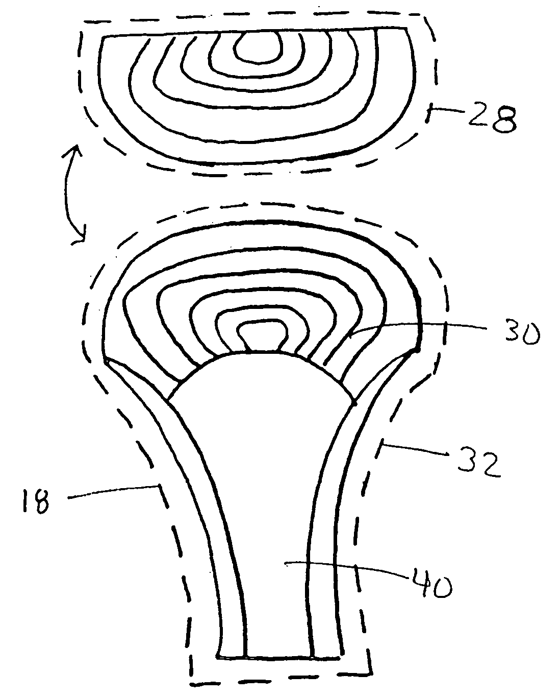
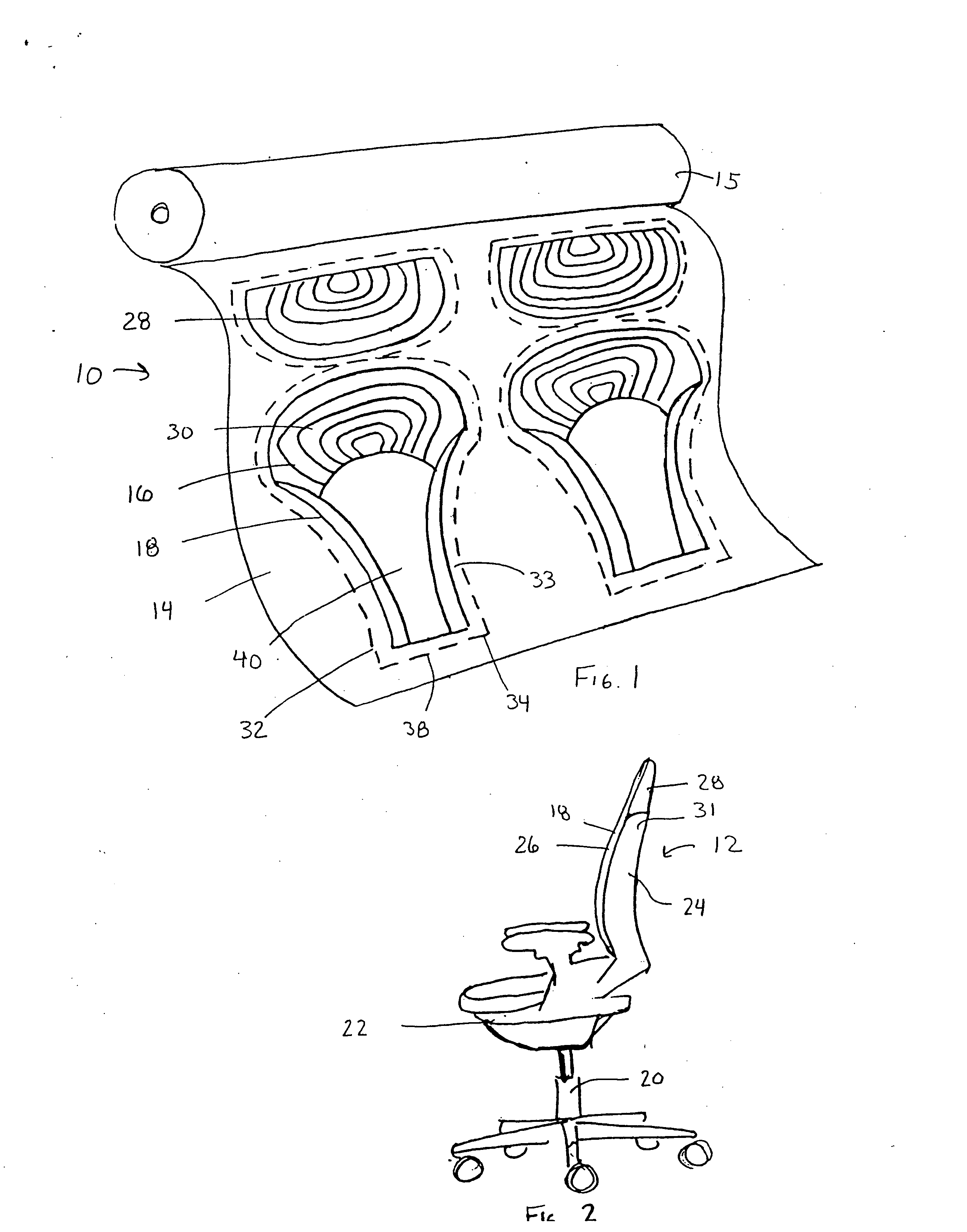
[0077] A textile component in accordance with a first embodiment of the present invention is shown in FIG. 1, and generally designated 10. In this embodiment, the textile component is shown in connection with an office chair 12. For illustrative purposes, the component 10 will be described in connection with the particular office chair 12 shown, however, the component 10 is adaptable for use with many different applications, including a variety of seating applications, such as, pedestal chairs, residential, automotive and transportation seating. Shown in FIG. 2, the chair 12 generally includes a base 20, a seat component 22, and a back support component 24.

[0078] As shown in FIG. 1, the textile component 10 is generally woven into a web of fabric 14. The web 14 may be formed into a variety of widths and lengths, and formed out of a variety of fibers and yarns set at a variety of end counts (number of yarns per inch in the warp) and pick counts, (number of yarns per inch in the fill...

Example

II. Second Embodiment

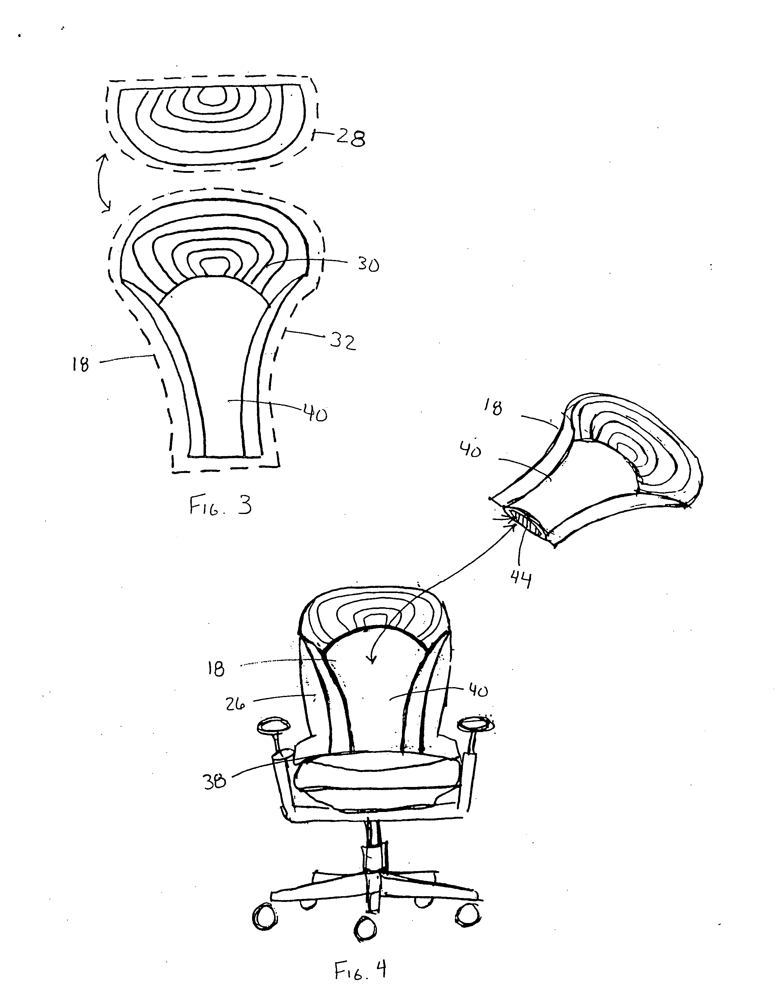
[0090]FIGS. 40-50 show a second embodiment of the present invention, wherein the textile component is attached to a privacy screen. As shown in FIG. 40, the textile 100 is formed by the jacquard method into a web 102 and disposed on a roll 104 similar to that described in the first embodiment. In this case, the web 102 includes a series of repeating (or non-repeating) patterns 106, that can be divided into panels 120. The patterns 106 may each include a desired design 108, and a periphery 110. The peripheries 110 of each sequential pattern may be separated by a cut line 112. The cut line 112 is similar to the cut lines 34, 64 described in connection with the first embodiment in that it is typically a binding weave that defines the periphery 110 of the pattern and is distinguishable from the rest of the web 102 and the design 108. After the web 102 is formed, the individual panels 120, shown in FIG. 44, may be separated by cutting along the cut line 112 with a c...

Example

III. Third Embodiment

[0093] A third embodiment of the present invention is shown in FIGS. 51-52 and FIGS. 54-56. In this embodiment, the textile component 200 is shown attached to a lampshade base 202. As shown in FIG. 56, the lamp shade base 202 includes a weight 204, a stem 206, four cross members 208 arranged in approximately a square, a pair of vertical support beams 210 extending from each corner of the cross members 208. In order to attach the textile component 200 to the base 202, four panels 212 are positioned in a square, with a pair of channels 214 extending over each pair of beams 210. As shown in FIG. 51, the textile component 200 is formed on a roll 216 similar to the first two embodiments. In this case, the fabric 200 includes cut lines 218 every fourth panel 212 to form a web 215 (shown in FIG. 54) of sequential panels that will remain connected for attachment to the base 202. Shown in FIG. 54, the cut lines 218 define a margin 220 at the periphery of each web 215. T...


PUM


Abstract

A textile component includes pockets and/or channels woven directly into a fabric web using a jacquard or dobby weaving method. The textile component may be used in a variety of applications for attachment to an article or structure. In addition, the component may include a seam/cut line formed by a binding weave and a seaming weave defining the perimeter shape of the textile component and defining an intended path for a cutting device. The component may be woven inside out so that the binding and seaming weaves conceal the seam when the component is turned inside out. A decorative pattern or motif can be woven with reverse weaves so that, when the component is turned rightside out, the decorative face is exposed.

Description

RELATED APPLICATION [0001] The present invention is a continuation-in-part of U.S. application Ser. No. 10 / 913,741 which was filed on Aug. 6, 2004 (now U.S. Pat. No. ______). This application claims priority to U.S. application Ser. No. 10 / 913,741, which was filed on Aug. 6, 2004 (now U.S. Pat. No. ______).BACKGROUND OF THE INVENTION [0002] The present invention relates to woven textile components, and more particularly to textile components formed by a jacquard weaving method, and in some cases by a dobby weaving method, for covering an article. [0003] Decorative and plain fabrics are well known for use in a wide variety of applications, such as upholsteries for seating applications, office partitions, and accessories. These fabrics are generally woven fabrics that have particular designs, patterns, and colors, depending on the application. The patterns and designs are generally woven into a large web of fabric on a loom. The web of fabric is commonly woven for a desired length, an...

Claims


Application Information

Patent Timeline
IPC IPC(8): A47C7/02A47C31/02
CPCA47C31/11D03D1/04D03D11/02E04B2/7422E04B2002/7479
Inventor ZAHARAKOS, ANNA E.
Owner STUDIO Z TEXTILES
Why Eureka
Try Eureka